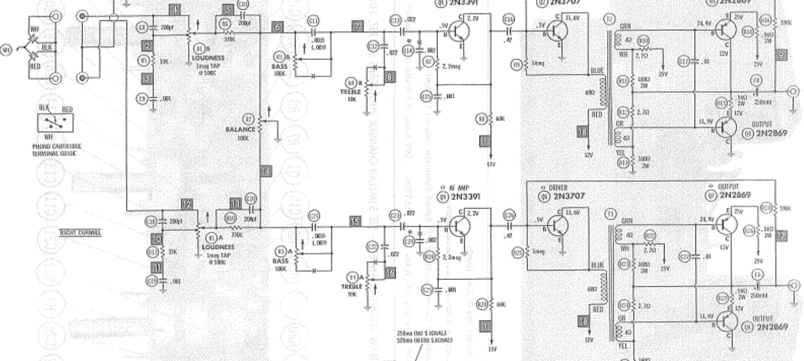
Trying to repair a vintage phonograph. Schematic attached.
Anyway - one channel (right) was weak and distorted, so I suspected the output transistors from the start but didn't have a schematic yet to debug. I'm an old guy relearning electronics from scratch again, so I figure the safest thing to do was get the schematics and walk through the audio path from the input on. Eventually I think I did confirm that one of the output transistors was bad (Q8 in the schematic). The schematic labels the four output transistors as 2n2869 but the actual transistors currently installed are 30203's so not sure if they had been changed at some point. Any, using a multimeter I did a diode check between the Collector and base and again C/emitter, and see a very low voltage .09 whereas I think it's supposed to be between .4 and.9 (tens times higher). With Neg on Collector and Pos on Emitter I get 0v, and open when moved to the Base. Swapping to Pos on the collector, I again get 0v to the emitter but .09 to the base. So my questions are:
1) Some please confirm this is a bad transistor?
2) Assuming it is, what would be the impact to the circuit if I put a 2N2869 in as a replacement, which is what is listed on the schematic. Any substantial volume increase/decrease on that channel as a result? Actually not looking for more power, just what the volume to be level across the channels? Of course the 30203 will be the closest match since it's the same as the other 3 currently install, I just want to understand my options and the impact if I go the other part number.
3) Are there any good source for online replacements - at low cost and used is ok. I obviously searched EBAy (and surprisingly only a couple hits there) and did a quick google, but both of these parts generally come up in the $20-$35 price range which honestly is a more than I think it is worth to fix up this unit. I've already put in about $15 for some caps and it's getting to be more an expensive venture than I had planned for what it is. I did find one source that had the 2N2869 for $9 (plus shipping) at even that will be at the edge of my $$ tolerance I think for the entire unit expenditure (original price plus parts)
4) Somewhat unrelated, as I was debugging the audio path, I was using a small battery powered amp to trace the audio through the circuit. Note that my input source was not actually the phonograph. I had disconnected that for logistics & testing reasons and hooked up a cassette player. Obviously a different gain/impedance input and perhaps that has something to do with my debugging problem I'm about to explain. In the schematic, at test point 5 (or 13 for the other channel) whihc is right after the volume control the audio is loud and clear. As loud as if I had connected directly to the input source itself (as long as the volume set to 100%). All good there. However, right after the next stage (channel balance at test point 6 or 14) the audio volume is severely diminished and I don't understand why. That is with the balance set at 50% (and it works appropriately swinging to the left or right channels). As I said I still learning but with that result I would have initially thought I had a dead preamp circuit from that point forward - yet the unit runs fines with lots of volume (except on the right channel with the bad transistor of course) so obviously it's getting all it's gain back in later stages, but I don't understand the circuit design and why the gain loss right at the balance stage. What in the circuit causes that severe signal attenuation at that point and is that normal? Is it related to the audio source I'm using and some kind of expected impedance or voltage mismatch? I'm not sure if the Parallel RC just prior to the balance is the reason (or even what purpose that circuit there serves?) While none of this is the cause of my real problem (bad transistor) I just wanted to understand the theory behind what I am seeing occur. Thanks

Transistor replacement and some audio circuit understanding
Electrically amplified phonographs or radio/phonographs and related components (approx. 1928-1990).
-
 MattTech
- Senior Member
- Posts: 1461
- Joined: Tue Apr 29, 2008 7:38 am
- Location: Philadelphia Pa USA - Home Electronics - Service Technician
2N2869 & 30203 are both TO3 germanium output transistors.
And expensive these days.
30203 is the factory original.
Knowing the voltage drop of these devices compared to Silicon devices, they seem normal.
I doubt the one suspect is bad, but possibly due to defective coupling caps it can be stressed.
Checking for 1/2 B+ at the positive side of the speaker coupling caps will show if balanced and working properly.
As for the gain drop at the balance - clearly shows a voltage divider there, so of course apparent levels are going to be lower at that point.
These are common VM amps used in a lot of their solid state sets.
The Internet is a marvelous thing, however it's not a good substitute for actually being there.
Checking for 1/2 B+ at the positive side of the speaker coupling caps
I assume that's my same - too fast typing typo - and you meant V+. Which cap are you referring to C6/250 mfd cap or C7/2mfd cap? The latter wasn't previously shown in the diagram I attached. I attached a zoomed in version of that output stage with that sections added (though still just as hard to read, original scan is very poor)
As for the transistor versions - do you see them as interchangable or with it be noticeably unmatched if one of the 4 is a 2n version? (Even if I don't need one I still want to know for the future)
As for the voltage divider circuit I wanted to understand the theory behind it's use there. Is is to get the input gain down to a level that the AF AMP (Q1/Q5) can handle? I'm trying to understand why cut the voltage only to boost it later.
- Attachments
-

- VM369-outputstage.jpg (116.42 KiB) Viewed 905 times
Update - I'm sure that Q7 transistor is blown. Diode checked/measured all the pin combinations on all 4 transistors. Only Q7 had 0V between Collector and Emitter in both directions. The others had 1v or just under from Cn to Ep and infinite in the other direction.
So I'm pretty sure I'm back to my original question - 2N2869 a valid alternative (since I can get one relatively cheaper) or any good sources for a low cost 30203?
So I'm pretty sure I'm back to my original question - 2N2869 a valid alternative (since I can get one relatively cheaper) or any good sources for a low cost 30203?
Think about it... These transistors are in a push-pull arrangement and would have to be replaced in matched pairs for it to function properly. I had 2 bad ones in my Zenith and ended up replacing all 4 output transistors with a matched set to repair it properly.
Vinyl is disease which attacks that area of the brain desiring digital recordings. Once you catch it, you are cured.
-
MattTech
- Senior Member
- Posts: 1461
- Joined: Tue Apr 29, 2008 7:38 am
- Location: Philadelphia Pa USA - Home Electronics - Service Technician
Thom wrote:Think about it... These transistors are in a push-pull arrangement and would have to be replaced in matched pairs for it to function properly. I had 2 bad ones in my Zenith and ended up replacing all 4 output transistors with a matched set to repair it properly.
That's right.
Ya either do the job properly, or not at all.
Matched pairs replacements are always mandatory, not an option.
The Internet is a marvelous thing, however it's not a good substitute for actually being there.
-
Ron Rich
- Forum Moderator
- Posts: 8193
- Joined: Sun May 06, 2007 11:31 pm
- Location: Millbrae (San Francisco area)CA, USA
Guyz--
Back in "the old daze"--the company I worked for matched output trannies with a color dot, to signify a match. They insisted all through the days that they used the flower type trannies, that they MUST BE matched (by color dot), but only within a channel. The "balance pot" took care of any differences between mis-matched channels. When they started using the "sand " style, they dropped the matching requirement, and stated only "it's best to use the same BRAND trannies in a channel--but not entirely necessary".
I have stuck with this for years--germanium's get replaced in matching pairs, ONLY, while the silly-cones get only "matched brands".
Works for me ?? Ron Rich
I have to tell ya Ron I prefer to work with tubes, not trannys but I make exceptions for sets like my Zenith. I hadn't taken much time to think of the differences between germaniums and sand. It would make things easier.
Vinyl is disease which attacks that area of the brain desiring digital recordings. Once you catch it, you are cured.
-
 Record-changer
- Senior Member
- Posts: 1139
- Joined: Fri Apr 21, 2006 8:11 pm
- Location: Bloomington IN USA
It is very hard to test a transistor in circuit. It is better to disconnect the base first.
Who is online
Users browsing this forum: No registered users and 3 guests
It is currently Thu Oct 06, 2016 7:57 am