Mike,
I'm totally confuzzed--- what's a 1645, and what does it have to do with a MRA-4 ? Ron Rich

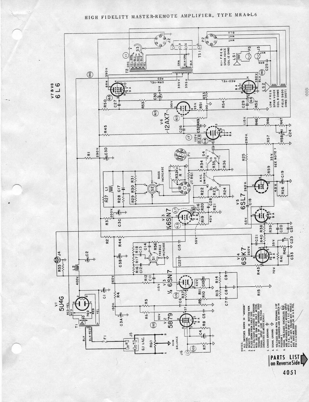
Seeburg MRA4 L6
Q&A about all types of jukeboxes: Wurlitzer, Seeburg, Rock-Ola, AMI, and more.
-
Ron Rich
- Forum Moderator
- Posts: 8196
- Joined: Sun May 06, 2007 11:31 pm
- Location: Millbrae (San Francisco area)CA, USA
Re: Seeburg MRA4 L6
by Ron Rich » Mon Mar 30, 2015 9:24 pm
-
mike11
Topic author - Regular Member
- Posts: 45
- Joined: Mon Oct 13, 2014 8:11 am
- Location: scranton PA USA
Re: Seeburg MRA4 L6
by mike11 » Mon Mar 30, 2015 9:30 pm
the replacement hammond 1645 transformer
-
Ron Rich
- Forum Moderator
- Posts: 8196
- Joined: Sun May 06, 2007 11:31 pm
- Location: Millbrae (San Francisco area)CA, USA
Re: Seeburg MRA4 L6
by Ron Rich » Mon Mar 30, 2015 9:39 pm
I have never used one--sorry-- no paperwork with it ?
Ron Rich
Ron Rich
Re: Seeburg MRA4 L6
by Rob-NYC » Wed Apr 01, 2015 2:47 am
Mike, sorry for the delay. I think i'm looking at the same tran you ordered and because of the way it was designed and the limitation of the seeburg speaker switch, it looks as though you can wire it for only one types of output at a time.
The internal speaker is 8 ohms, so the diagram at the bottom right on that page shows that black and black-yellow are tied together and for our purposes they will be connected to chassis ground as per the original tran.
Then green and green-yellow are tied together but not connected to anything else.
The output to the speaker is the yellow wire. That wire should be connected to the "20 watt" terminal on the speaker switch since that (IIRC) is also where the feedback wire is connected.
Individually insulate- tape any unconnected wires.
Rob-NYC
"If we believe absurdities, we shall commit atrocities" -- Voltaire
-
mike11
Topic author - Regular Member
- Posts: 45
- Joined: Mon Oct 13, 2014 8:11 am
- Location: scranton PA USA
Re: Seeburg MRA4 L6
by mike11 » Wed Apr 01, 2015 6:59 am
As long as I can get this going with the cabinet speakers were good ....... Seems this has 1 less lead than the original ..... That's where the confusion came in with the switch ...... Wire for 8 and set switch at 8 and I'm good ???
-
mike11
Topic author - Regular Member
- Posts: 45
- Joined: Mon Oct 13, 2014 8:11 am
- Location: scranton PA USA
Re: Seeburg MRA4 L6
by mike11 » Wed Apr 01, 2015 7:01 am
Wire for 8 and set the switch at 8 and I'm good ???? That's where the confusion was coming in it seems the original had more leads
-
mike11
Topic author - Regular Member
- Posts: 45
- Joined: Mon Oct 13, 2014 8:11 am
- Location: scranton PA USA
Re: Seeburg MRA4 L6
by mike11 » Wed Apr 01, 2015 7:02 am
Sorry for the dbl post I didn't think it posted ..... Damn phone
Re: Seeburg MRA4 L6
by Rob-NYC » Wed Apr 01, 2015 9:29 am
Mike, as I see it one pair of wires go to the same chassis ground as the previous tran and the other pair should go to the highest watt tap as shown on this schematic:
http://www.verntisdale.com/schem/mra4-l6.jpg
Note that there is a feedback wire that must go to the highest watt tap too.
Since there is now only one wattage available you could just connect both tran and feedback wires directly to the pin on the speaker socket thus eliminating the switch.
These later transformers are a lot more efficient than the originals and have better frequency response as well. Since they pass more power there is the remote chance the speaker might be over-driven so use a little caution with the bass if you plan on high levels.
Rob
"If we believe absurdities, we shall commit atrocities" -- Voltaire
-
mike11
Topic author - Regular Member
- Posts: 45
- Joined: Mon Oct 13, 2014 8:11 am
- Location: scranton PA USA
Re: Seeburg MRA4 L6
by mike11 » Thu Apr 02, 2015 9:39 pm
Rob-NYC wrote:Mike, sorry for the delay. I think i'm looking at the same tran you ordered and because of the way it was designed and the limitation of the seeburg speaker switch, it looks as though you can wire it for only one types of output at a time.
The internal speaker is 8 ohms, so the diagram at the bottom right on that page shows that black and black-yellow are tied together and for our purposes they will be connected to chassis ground as per the original tran.
Then green and green-yellow are tied together but not connected to anything else.
The output to the speaker is the yellow wire. That wire should be connected to the "20 watt" terminal on the speaker switch since that (IIRC) is also where the feedback wire is connected.
Individually insulate- tape any unconnected wires.
Rob-NYC
the highest wattage I have is 16.... yellow to 16 term ?? and the white wire ???
the remote speaker terms will have nothing to then when done correct ???
as far as the input side that drawing looks to be a mirror image in either direction so starting from the top of each drawing and wiring working down I should be ok ?yes
Re: Seeburg MRA4 L6
by Rob-NYC » Fri Apr 03, 2015 10:17 am
Mike, I don't have one of those older amps here, but I believe the white wire is the negative feedback lead and it should be connected to the same terminal that the 8 ohm high side is (yellow from tran).
Other than the black wire to chassis ground, none of the other terminals will have connection.
As for the wattage difference, it will be few watts higher with the new tran due to better efficiency but that will not be audible. The overall sound will be better when hooked up correctly.
Rob
Other than the black wire to chassis ground, none of the other terminals will have connection.
As for the wattage difference, it will be few watts higher with the new tran due to better efficiency but that will not be audible. The overall sound will be better when hooked up correctly.
Rob
"If we believe absurdities, we shall commit atrocities" -- Voltaire
-
mike11
Topic author - Regular Member
- Posts: 45
- Joined: Mon Oct 13, 2014 8:11 am
- Location: scranton PA USA
Re: Seeburg MRA4 L6
by mike11 » Fri Apr 03, 2015 7:42 pm
I just want to be 100% sure this is right when I power it up...... heres the mra4 schem
http://arcarc.xmission.com/PDF_Jukebox/ ... ra4-l6.pdf
heres the 1645 schem the 1645 wiring is lower on the page......
http://www.hammondmfg.com/1608.htm
its showing the white as 70v.... are we using that ?
as it sits I done as you said
BLK-BLK/YEL to ground
GRN-GRN/YEL butted together NC
YEL to highest switch output
Im left with the white thats it
Im not familiar with sound amps at all ...im sorry for all the questions i just dont wanna cook this i am helping a friend out with it and dont wanna ruin his stuff
Thanks you very much
-
mike11
Topic author - Regular Member
- Posts: 45
- Joined: Mon Oct 13, 2014 8:11 am
- Location: scranton PA USA
Re: Seeburg MRA4 L6
by mike11 » Fri Apr 03, 2015 8:34 pm
It's the white 70v tap off the trans that's left that has me concerned ..... Can that be left floating ??
Re: Seeburg MRA4 L6
by Rob-NYC » Sun Apr 05, 2015 7:52 am
mike11 wrote:It's the white 70v tap off the trans that's left that has me concerned ..... Can that be left floating ??
Yes, you can just tape it up.
The (possibly) white wire that I was referring to is the feedback wire on the amp itself which must be connected to the high side connection of the 8 Ohm connection, the yellow wire from the tran.
You are only using the wires depicted in the lower right diagram for 8 Ohms.
Rob.
"If we believe absurdities, we shall commit atrocities" -- Voltaire
-
mike11
Topic author - Regular Member
- Posts: 45
- Joined: Mon Oct 13, 2014 8:11 am
- Location: scranton PA USA
Re: Seeburg MRA4 L6
by mike11 » Sun Apr 05, 2015 8:15 pm
Thank you ... now I wont be afraid to power this up...... I see the feedback wire your referring to that was already on the switch post in the original wiring
Who is online
Users browsing this forum: Bing [Bot], Google Adsense [Bot] and 10 guests
It is currently Thu Oct 06, 2016 9:45 pm
- Delete all board cookies
- All times are UTC+02:00