Page 2 of 2
Re: Remote Vol Wiring
Posted: Wed Jul 30, 2014 5:33 am
by Ron Rich
Hi James,
Yep--somehow, what we have here is a failure to communicate --I'll try again--
The socket in that photo, IS the one that holds either the Dummy plug OR, a plug connected to another (remote) VC.
When a "dummy plug" is installed in that socket it "jumps" the internal volume control into the circuit. If an outside remote VC is desired, the dummy plug needs to be removed, and a new plug inserted in that socket. This new plug is wired so that it substitutes the external control for the internal one.
Hope that clears it up--
Ron Rich
Re: Remote Vol Wiring
Posted: Wed Jul 30, 2014 4:30 pm
by James_Douglas
Ok Ron,
Now we are both on the same dance card.
The question now is...The remote VC and its plug. Is it wired, pins wise, the exact same way as the on-board VC and/or does it also include the jumper wires that the dummy plug used?
James
Re: Remote Vol Wiring
Posted: Wed Jul 30, 2014 4:48 pm
by Ron Rich
James,
Look at the schematic--page 4038 for the VC plug dummy plug (and socket), wiring--
Look at page 8006 for the "remote" wiring--
Either "plug", ONE, at a time, can be used to connect "A" volume control (remote, or internal) to the amp.
Ron Rich
Re: Remote Vol Wiring
Posted: Wed Jul 30, 2014 7:31 pm
by Rob-NYC
Ron Rich wrote:James,
As Rob mentioned--there should be zero connections to the internal volume control, when using a "remote". One of Rob's
"Geppeto friends" must have been "playing around" and hard wired it to the socket. Ron Rich
Yep, except that all my 'friends" in that business are long-gone. Smoking (and yuppie condos) cut a swath through everybody down there on Tenth Avenue.
I will admit that I considered tacking-on jumpers instead of the RVC dummy because after some years of service, rocking the plug shows that resistance has built-up.
Rob
Re: Remote Vol Wiring
Posted: Wed Jul 30, 2014 8:14 pm
by James_Douglas
What I do not get is that:
The original VC on the AMP is wired to pins 3,4,5, and 6 and pins (2-3)(1-4)(5-7) are jumped in the dummy plug.
The MRVC uses pins 1,2,6, and 7 and shows nothing in the schematic about jumping any pins.
Can anyone clear this up for me as I am totally confused. Attached is the only two schematics I have from the service manual that I have.
James
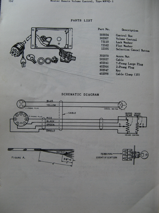
- MRVC_1_small.jpg (295.23 KiB) Viewed 465 times
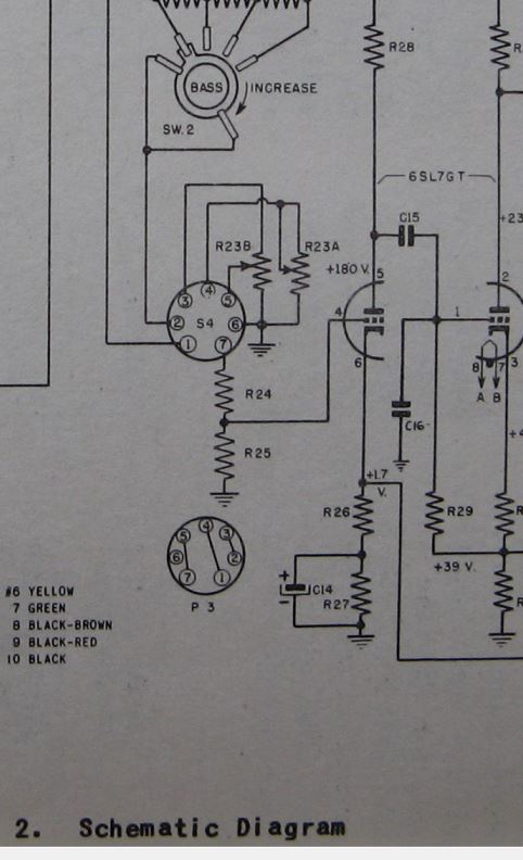
- Volume_Wiring.JPG (57.1 KiB) Viewed 465 times
Re: Remote Vol Wiring
Posted: Thu Jul 31, 2014 1:32 am
by Ron Rich
Hi Jim,
They were simply using pins 3,4, and 5, as storage for the internal VC wires. Pins 1.2, and 7, are the "active" ones. When the dummy is inserted it "JUMPS" the inactive (storage) pins to the active ones. If using a remote plug, you don't want, nor need to jump anything, just go directly to the active pins.
If you wanted to, you could clip the wires that are on the storage lugs, and solder them directly to the active ones, remove and discard the dummy plug. I have done this a few times, in an "emergency", when the dummy socket was "messed up", or the dummy plug was missing--
Ron Rich
Re: Remote Vol Wiring
Posted: Thu Jul 31, 2014 1:54 am
by James_Douglas
Hi Ron,
I guess then I misunderstood what you suggested when you said to wire my remote VC like the one in the AMP.
I need to go back make sure the wiring to the pins on the plug coming from the RMCV-1 POT's match the schematic for the RMVC-1 above rather than try and duplicate the wiring-pin assignments for the VC on the AMP.
I also need to talk with you about arranging a trip up here to look at the AP1. Moving that thing is a pain!
James