Tony, if the box is missing a transformer on the upper left in this pic:
http://s1192.photobucket.com/user/Rob-N ... rt=2&o=199 -that is an (asinine IMO) J.R. mod which means you'll have to use 28 volt bulbs.
If you have a standard coin validator as shown in the center, it should be a simple matter to revert the rejector adjustments to allow all coinage to pass -IF the 'holes didn't remove parts there as well.
It looks like on of the leaf switches was removed that are shown here:
http://s1192.photobucket.com/user/Rob-N ... rt=2&o=200 -which one?
From what I can see of the title strips it does look like those that were generated by the mid-nineties computer program they were using.
For all the hacking these "people" did to these boxes, in nearly all cases where I have actually seen them in their stores, they were consistently dark and in most cases didn't work at all.
As for the wire, tripling the copper of #24ga will still not get you to 20ga which I would consider as minimal for this sort of application. However, if you use no more than 2amp fuse and the run does not cause more than 10-15% loss while sending, it will probably be Ok. The safety problem arises when a long run of undersized (for the current) cable becomes too much of a resistor. It then becomes effectively the fuse and heats up instead of the actual fuse, that can lead to a fire in the case of a fault in the box or wiring.
The way I've dealt with this in locations I took over that has questionable wiring was to determine the fuse needed and then to momentarily place a dead short across the line at the farthest point. If the fuse blows within 1 or 2 seconds I consider that enough of a margin.
Rob/NYC

Using a Seeburg 3W1 Select-O-Matic with
Q&A about all types of jukeboxes: Wurlitzer, Seeburg, Rock-Ola, AMI, and more.
"If we believe absurdities, we shall commit atrocities" -- Voltaire
-
Color jockey
Topic author - Regular Member
- Posts: 42
- Joined: Mon Nov 25, 2013 9:22 am
- Location: Los Angeles, California, USA
Thanks Rob. This confirms that it is a J/R mod. No transformer, no leaf switch, God only knows what else! What did the leaf switches do? I assume that is where the blue wires went. What was the purpose of this mod? Removing the lighting transformer, removing switches, nickel play only, etc. is this going to effect the operation of my 100G? I just wanted to get a 3W1 to control my jukebox, now it looks like I have Franken-O-matic. Will this ever control my 100G?
Thanks again!
-Tony
Thanks again!
-Tony
Will this ever control my 100G?
Of course it will -once it and the stepper are working properly. From what I recall, J-R used several systems to run the wallboxes. A CD changer interface and then a PC interface. Both used the original pulse train from the wallboxes.
I don't have any info on the 3W1 but they are so simple and I do have these, somewhat musty sheets for the 3W100 which succeeded it:
http://s1192.photobucket.com/user/Rob-N ... rt=2&o=201
http://s1192.photobucket.com/user/Rob-N ... rt=2&o=202
Again, what is the state of the stepper? A test is intermittently tapping a short with the blue signal line to chassis ground Doing so should cause the stepper to step up and if done properly with a brief pause between two trains of pulses it will transfer from letters to numbers and actually write-in a selection.
Rob
"If we believe absurdities, we shall commit atrocities" -- Voltaire
-
Ron Rich
- Forum Moderator
- Posts: 8193
- Joined: Sun May 06, 2007 11:31 pm
- Location: Millbrae (San Francisco area)CA, USA
Hi Rob, Tony,
I have "serviced" a few hundred of these JR "updated" 3W1's, In almost every case where they have had "coin problems" I have found that the rejector was hacked differently--or so it seemed ! I have seen parts removed, parts glued so they can't move, and parts "bent"--
-----------------------------------------------------------------------------------------------------------------------------------------------------------------
Tony,
If you wish to restore the WOM, contact some of the suppliers listed above in the "announcement/sticky section ". I would think most of them would have the autoformer, and a non-"updated" slug rejector.
As for the three switches, with the orange wires on them, they were NOT used by the factory--they were jumped on all production runs--see the service manual for the optional use of these switches .
Also--FYI--the WOM has no "control" or bearing on whatever the main phonograph does--it merely, when properly running, can trigger the stepper section in the WSR, to activate. If the WOM and the stepper are operating as they should, this causes a selection pin in the SAUnit to move to the selected state (exactly the same thing that the ES on the phonograph causes) . Ron Rich
.
Ron Rich
Hi Rob, Tony,
I have "serviced" a few hundred of these JR "updated" 3W1's, In almost every case where they have had "coin problems" I have found that the rejector was hacked differently
Ron, I've owned a between 160 and 170 wallboxes and have 121 of them on location. Believe me, if there is something stupid that can be done to these things, I've seen it.
In 1996 a J-R opened in Hoboken NJ and my jukebox friend and I decided to go over and see it. It had been open for a few months, but already, the table we sat at had a jammed 3W1. I mentioned that we work on these things and the owner or manager came over and handed me a key to open it. that was when I saw the absent transformer and my friend Bill saw a hacked rejector. The hacks looked reversible and I asked the owner if he would like it to take quarters instead of just nickels. He replied that "he would" but it J-R franchise policy was nickels only. We then fixed three more boxes and replaced some light, he comp'ed our meals and asked for our phone #'s.
As I mentioned before, I don't know what arrangements they make for servicing these systems, but whenever I've been in those places most boxes are dark and don't work. I don't care to get involved.
Rob
"If we believe absurdities, we shall commit atrocities" -- Voltaire
-
Ron Rich
- Forum Moderator
- Posts: 8193
- Joined: Sun May 06, 2007 11:31 pm
- Location: Millbrae (San Francisco area)CA, USA
Hi Rob,
JR's opened 4-5 stores in this area, and "called around" to the various operators for service--they "bounced' from op, to op, including myself, always wanting to "sign a contract", for a set amount, per week--I never wanted to sign any contract, so, they kept on looking---
Last time I was in a JR's, all 3W-1's had been replaced with "JR's boxes" (RockOla built). I could not hear the system functioning, and all coin chutes were covered with tape. (The "pulls" are being solt on eBay, in most cases, without mentioning that they were JR pulls, at IMHO, high prices--always noting the "chrome is great" in the write-up--clue here is the Nickel ONLY, coin window--never offered by Seeburg !) Ron Rich
-
Color jockey
Topic author - Regular Member
- Posts: 42
- Joined: Mon Nov 25, 2013 9:22 am
- Location: Los Angeles, California, USA
Rob-NYC wrote:
Check the 100 ohm resistor on the tube plate circuit. Be sure that the large 5mfd capacitor in the 2050 plate circuit has been replaced.
Rob/NYC
Rob, you mentioned replacing the 5mfd cap in the 2050 plate circuit. I have located it and it is the original. I noticed that it is in a square metal case. Is that designed to shield it from noise? Is it grounded to the chassis, or can I replace it with a standard electrolytic 300v 5uf capacitor?
Thanks.
-Tony
Tony, the 5 MFD is a non-polarized type because it is used for AC. You can get a "motor start' cap of 5MFD @200 volts ot more, or you can use what I use:
http://s1192.photobucket.com/user/Rob-N ... sort=2&o=1
Those are Mylar caps as used in a Seeburg stepper. Alternately, two polarized electrolytic caps of 10Mfd ea can be placed back-to-back with the can (negative) leads together to obtain 5 Mfd. Use caps of at least 200Volts Dc. If you go this route it helps if you can measure the resulting capacitance because electrolytic caps are not as accurate as the mylar and accuracy is important here in preventing miss-counts.
Rob
"If we believe absurdities, we shall commit atrocities" -- Voltaire
-
Color jockey
Topic author - Regular Member
- Posts: 42
- Joined: Mon Nov 25, 2013 9:22 am
- Location: Los Angeles, California, USA
Rob-NYC wrote:Tony, the 5 MFD is a non-polarized type because it is used for AC. You can get a "motor start' cap of 5MFD @200 volts ot more, or you can use what I use:
http://s1192.photobucket.com/user/Rob-N ... sort=2&o=1
Those are Mylar caps as used in a Seeburg stepper. Alternately, two polarized electrolytic caps of 10Mfd ea can be placed back-to-back with the can (negative) leads together to obtain 5 Mfd. Use caps of at least 200Volts Dc. If you go this route it helps if you can measure the resulting capacitance because electrolytic caps are not as accurate as the mylar and accuracy is important here in preventing miss-counts.
Rob
Thanks Rob. I also just noticed someone has clipped and insulated the tip of one of the Transformer 1 (T1) wires. My guess is brown. Any idea why someone would do that? And where in the hell does it go? I am trying my best to follow the schematics, but the colors are very difficult to see.
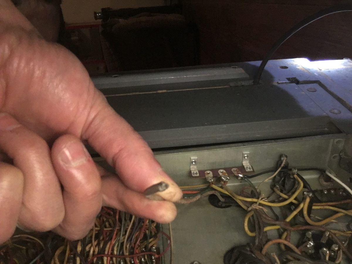
- image.jpeg (1018.62 KiB) Viewed 353 times
- image.jpeg (1018.62 KiB) Viewed 353 times
Tony, I don't know what to say about the wire. Does the machine work in all other modes excluding stepper?
If so, measure the plat of the stepper tube @pin 3. There should be approx 150Volts Ac to chassis. Check also the resistor on that pin. These often burnout when the stepper line shorts.
Check for a -25Volts DC @ Pin 5. If you have these voltages with a good resistor, the stepper should at least attempt to step up. It won't run properly if the 5MFD is bad, but should show signs of life.
Rob
"If we believe absurdities, we shall commit atrocities" -- Voltaire
-
Ron Rich
- Forum Moderator
- Posts: 8193
- Joined: Sun May 06, 2007 11:31 pm
- Location: Millbrae (San Francisco area)CA, USA
Hi Tony,
What unit is that wire that has been cut, "live in'--The 3W1, or the WSR ??
Also, for the most part, ignore wire colors listed in Seeburg schematics written prior to the mid 1960's as they tended to use a different color, any time they started a new production run, or if they ran out of a color--which happened OFTEN-- Ron Rich
What unit is that wire that has been cut, "live in'--The 3W1, or the WSR ??
Also, for the most part, ignore wire colors listed in Seeburg schematics written prior to the mid 1960's as they tended to use a different color, any time they started a new production run, or if they ran out of a color--which happened OFTEN--
-
Color jockey
Topic author - Regular Member
- Posts: 42
- Joined: Mon Nov 25, 2013 9:22 am
- Location: Los Angeles, California, USA
The clipped wire is in the 100G. This is the latest:
I did a test with a 24v light bulb. I used the 25v+ wire and the signal. On both ends the light bulb flickers when a selection is made. So it appears that the 3W1 is operating properly, and that the cable connecting the two is adequate. While inspecting the inside of the 100G I noticed that there was a broken carbon resistor 47ohm (C3), also the original metal cased 5uf cap was still in line. My guess is that the cap shorted and overheated the resistor. I purchased a new resistor and 250v 5uf fan motor capacitor on Amazon. Hopefully that will be ok? I noticed that the selector receiver had all of the original caps so I ordered replacements for those too (couldn't find 200v so got 400v replacements). Fingers crossed…
-Tony
-
Ron Rich
- Forum Moderator
- Posts: 8193
- Joined: Sun May 06, 2007 11:31 pm
- Location: Millbrae (San Francisco area)CA, USA
Tony,
That "clipped wire" bothers me-- check all voltages from that transformer--Is that the correct transformer for that unit ?
Other than that--everything else sounds OK--Might check ALL resistors-- ?? Ron Rich
That "clipped wire" bothers me-- check all voltages from that transformer--Is that the correct transformer for that unit ?
Other than that--everything else sounds OK--Might check ALL resistors-- ?? Ron Rich
I noticed that there was a broken carbon resistor 47ohm (C3), also the original metal cased 5uf cap was still in line. My guess is that the cap shorted and overheated the resistor. I purchased a new resistor and 250v 5uf fan motor capacitor on Amazon. Hopefully that will be ok?
If that is a one watt right near the 2050 socket it is the plate resistor I mentioned. Seeburg used Guardian stepper relays of two different impedance. On the earlier stepper the coils were 500 ohm and later they were 700 ohm. On the later steppers that plate resistor was increased to 100 ohms. I replace them with ½ watt so as to act as a fuse if the signal line gets shorted. This protects the stepper coils from overheating, possibly developing shorted turns and burning up.
The capacitor can not kill the resistor. However, if the resistor is burned up it is possible that one of the stepper coils radically overheated and may have been damaged. The coil value is stamped in the tape around the coil. Trace out the wires from the coil, and measure it's resistance. A 10-15% variation is not generally a problem. They do not have to be disconnected for these tests.
Rob
"If we believe absurdities, we shall commit atrocities" -- Voltaire
-
Color jockey
Topic author - Regular Member
- Posts: 42
- Joined: Mon Nov 25, 2013 9:22 am
- Location: Los Angeles, California, USA
Rob,
I am going to start with replacing all of the old caps and that one broken resistor. As far as the transformer it looks original. Since the initial problem seems to be that the 2050 isn't receiving the signal from the 3w1 and I checked at the 3 pin plug, which was strong, and the tube tested good… I am going to keep my fingers crossed that the problem isn't related to the stepper relays or the wiring. Once I get the caps and resistor replaced I'll check the voltage at the areas you mentioned. Let's hope it checks out ok. If not, are you up for a repair job?
-Tony
Who is online
Users browsing this forum: Yahoo [Bot] and 5 guests
It is currently Thu Oct 06, 2016 8:53 am