Seeburg TSU1 has a few issues needs a total recap,power transformer has failed, and selenium rectifier is cooked.
Seems that power transformers cooking is very common on this particular unit and new transformers are both costly and not easy to obtain.
I'm thinking the selenium rectifier failed and the transformer failed due to no fuse being installed.
I intend to replace the selenium rectifier with a 25amp 400volt bridge rectifier a bit of overkill but it should fit in nicely and they are pretty cheap.
I will install a 1 amp fuse on the AC side of the bridge rectifier to try and protect the transformer (thanks Ron I read that tip from you somewhere on the net)
Any advice on other ways to prevent the transformer failing again would be appreciated ie more fuses?
I will check for out of tolerance resistors, are there other components that should be replaced?
Also noticed that although the power supply plug and lead has an earth installed but is not connected to the metal casing of the TSU enclosure, is there a reason for this?
Cheers
John

Seeburg TSU1 recap
Q&A about all types of jukeboxes: Wurlitzer, Seeburg, Rock-Ola, AMI, and more.
John. of the loads on that tran the selenium is the least likely to have caused that failure.
Seeburg switches at the ground (chassis ) return. This means that voltage is always present in various items such as coils. If a coil develops a short to its core it will stay conducting until it, or more often, the transformer winding burns out.
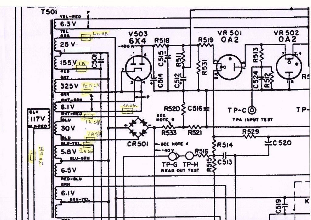
I fuse everything that comes out of that tran as follows:
LV-AC: (25 v) 4amp-slo
LV-AC (5 v) Decorative lights 1-2 amp-slo depending on load
150VAC (stepper and trip) 1 amp-fast
LV-DC 1 amp-slo each leg.
Tube heaters 5 amp-slo. That actual load is 3½ amp but the inrush will sometimes blow a 4 as I had originally used.
The primary should be tightened up also so I use a 3amp-slo.
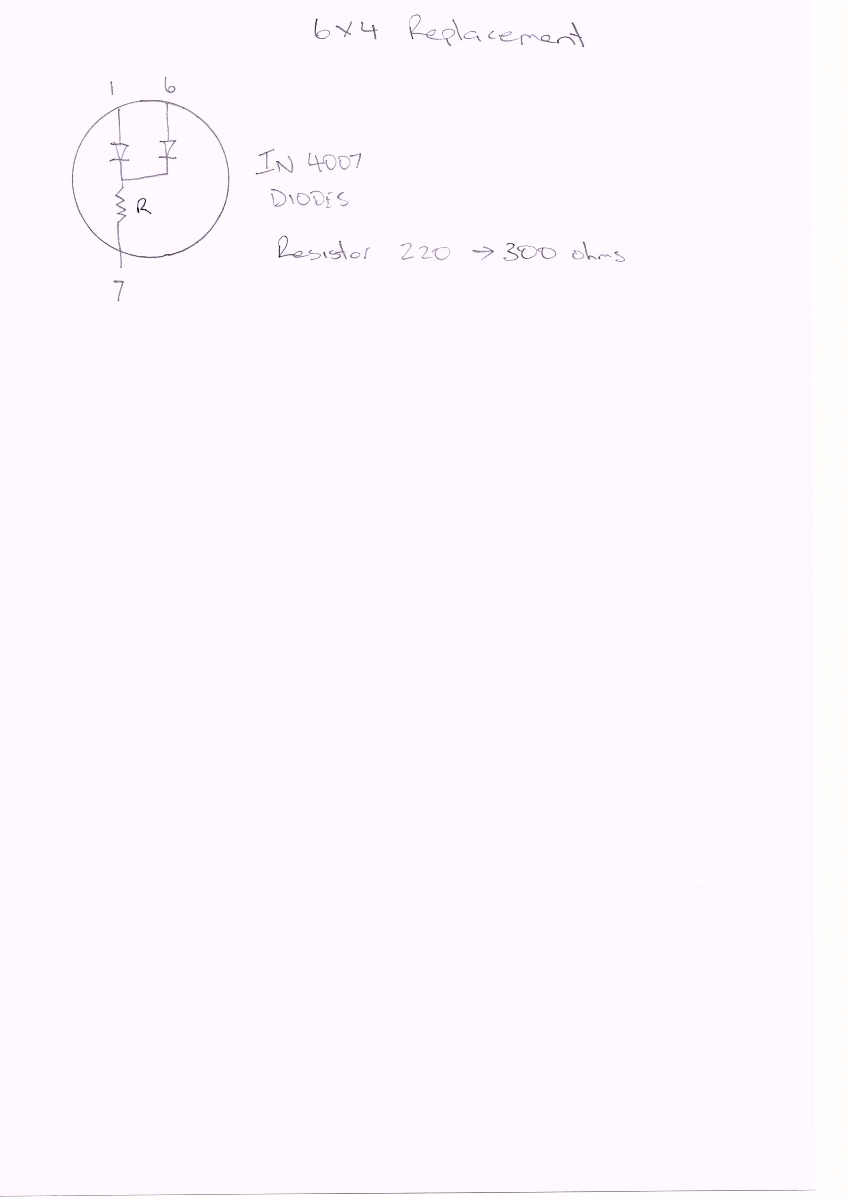
-Oops, forgot the most important one: HV-DC: ½-amp-slo in the lead to the 6X4. I use two diodes in series and a 220 to 300 ohm 5 watt resistor in place of the tube. Two of the control units i bought came with trans killed by shorted 6X4 tubes. There is no good reason for using a tube here.
In nearly 30 years of using old Seeburgs on location in retro locations I have only lost one main tran and that was due to a water leak over the machine. The locations was charged $500 for letting that happen.
Of all the manufacturers I've serviced, Seeburg was the only truly negligent one when it came to fusing. Best mechanism -worst protection.
Rob-NYC
Seeburg switches at the ground (chassis ) return. This means that voltage is always present in various items such as coils. If a coil develops a short to its core it will stay conducting until it, or more often, the transformer winding burns out.
I fuse everything that comes out of that tran as follows:
LV-AC: (25 v) 4amp-slo
LV-AC (5 v) Decorative lights 1-2 amp-slo depending on load
150VAC (stepper and trip) 1 amp-fast
LV-DC 1 amp-slo each leg.
Tube heaters 5 amp-slo. That actual load is 3½ amp but the inrush will sometimes blow a 4 as I had originally used.
The primary should be tightened up also so I use a 3amp-slo.
-Oops, forgot the most important one: HV-DC: ½-amp-slo in the lead to the 6X4. I use two diodes in series and a 220 to 300 ohm 5 watt resistor in place of the tube. Two of the control units i bought came with trans killed by shorted 6X4 tubes. There is no good reason for using a tube here.
In nearly 30 years of using old Seeburgs on location in retro locations I have only lost one main tran and that was due to a water leak over the machine. The locations was charged $500 for letting that happen.
Of all the manufacturers I've serviced, Seeburg was the only truly negligent one when it came to fusing. Best mechanism -worst protection.
Rob-NYC
"If we believe absurdities, we shall commit atrocities" -- Voltaire
-
Ron Rich
- Forum Moderator
- Posts: 8193
- Joined: Sun May 06, 2007 11:31 pm
- Location: Millbrae (San Francisco area)CA, USA
I agree here--I add two more fuses--
One on the primary side of the transformer--3A SB ( I leave the main 5 A MTH in place)
One AT the trip coil ( ON The mechanism, as if in the unit, a shorted coil will smoke the wiring all the way to and through the transformer) 1. AFB. Ron Rich
One on the primary side of the transformer--3A SB ( I leave the main 5 A MTH in place)
One AT the trip coil ( ON The mechanism, as if in the unit, a shorted coil will smoke the wiring all the way to and through the transformer) 1. AFB. Ron Rich
-
Faza1
Topic author - Regular Member
- Posts: 53
- Joined: Sun Jun 28, 2015 1:11 pm
- Location: Sydney, Australia
- img019a.jpg (144.49 KiB) Viewed 596 times
Would you be able to confirm i have this correct on the schematic?
Ron i will add a fuse to the trip coil inside the mech thanks.
Also Rob you mentioned replacing the 6x4 rectifier using diodes in series and a resistor to drop the voltage.
I would like to do this in the old rectifier base, should the diodes be in series or parrallel ?
Have i got it correct in the drawing or am i way off?
Also the earthing of the TSU enclosure is there a reason why they were never earthed originally?
Thanks for all the advice these transformers are really expensive and shipping to Australia tops it off.
John, the only issue I see is the fuse in the line going to the 6X4. 5 amp would be way too much and not needed at all if the tube is to be eliminated. My suggestion was to use that 5 amp fuse to protect the heater winding for the amplifier tubes. I have not done this on all machines, but it is a good idea.
Re: 6X4 Elimination; I remove the red wire from the tran that goes to pin 7 of the 6X4 and, as shown here, connect it to the first of two diodes:
http://s1192.photobucket.com/user/Rob-N ... rt=2&o=212
then through the resistor and onto the inline fuse holder (large red wire) and to the first filter as original.
The diodes used are whatever I have that can handle the current & voltage. Here they look to be 1KV-1amp.
This is from a TSU-7 (1962) whose transformer was ruined by a water leak. It was rebuilt by me in Feb. 1998 and used on location for approx 16 years w/no problems.
Rob
"If we believe absurdities, we shall commit atrocities" -- Voltaire
-
Faza1
Topic author - Regular Member
- Posts: 53
- Joined: Sun Jun 28, 2015 1:11 pm
- Location: Sydney, Australia
Thanks Rob really appreciate the help thought I'd make a start today and recap and check resistors on the pulse amp previous owner must have had problems with a intermittent contact between J509 socket and P502 plug so they built up the pins with solder.
The result was when the pulse amp was removed the socket pins pulled through the Bakelite.
Can replacements be purchased new or should I be looking at good used, manual part number is 301034 6 prong socket small.
Thanks
John
The result was when the pulse amp was removed the socket pins pulled through the Bakelite.
Can replacements be purchased new or should I be looking at good used, manual part number is 301034 6 prong socket small.
Thanks
John
John, I don't know of any alternative to taking a socket off a junked chassis. One good thing is that this was the same configuration used throughout the tube tormat era.
If this were my machine I'd just carefully reinstall the PA after rebuilding and place a taped note not to remove it on location. I have pulse amps in service for over 20 years so you are unlikely to need to remove it once properly serviced..
BTW: The large pins on that assembly have yet to give me any problem. Someone was just tinkering and probably "thought" this was a connection issue instead of whatever the problem really was.
Rob
"If we believe absurdities, we shall commit atrocities" -- Voltaire
-
Ron Rich
- Forum Moderator
- Posts: 8193
- Joined: Sun May 06, 2007 11:31 pm
- Location: Millbrae (San Francisco area)CA, USA
Hi John,
Somewhere, deep in my feeble memory, I seem to recall seeing this happen before--
Seems to me one of the AM-P, or Molex, crimp type connectors, fit the pins on the bottom of the pulse amp, perfectly ??
Ron Rich
Somewhere, deep in my feeble memory, I seem to recall seeing this happen before--
Seems to me one of the AM-P, or Molex, crimp type connectors, fit the pins on the bottom of the pulse amp, perfectly ??
Ron Rich
-
Faza1
Topic author - Regular Member
- Posts: 53
- Joined: Sun Jun 28, 2015 1:11 pm
- Location: Sydney, Australia
Thanks once again Rob / Ron.
I'm going to try and repair the 6 prong socket, i noticed today that the pickup plug has had a RCA socket installed and the mute wiring had been cut so I'm guessing this machine has had a different amp installed previously.
So I am also looking for the 3 pin plug for the pickup.
On a side note when replacing the selenium rectifier with a new bridge rectifier is it normal to put a resistor in to drop the voltage?.
Cheers
John
-
Ron Rich
- Forum Moderator
- Posts: 8193
- Joined: Sun May 06, 2007 11:31 pm
- Location: Millbrae (San Francisco area)CA, USA
Hi John,
On the PA socket--You do have one "unused" pin--you can jump both the plug, and socket, then use that unused position--
For the three pin plug---didja look at the suppliers listed here above this post--any of the used parts suppliers should have it as it was used on about 49 model Seeburgs
I do not replace the selenium unless ab-sol-lutly necessary ! If necessary I do so with a bridge which I fuse on the primary side -- no resistor is needed IMHO. Ron Rich
John, that plug is an Amphenol MC3M:
http://s1192.photobucket.com/user/Rob-N ... rt=2&o=213
Here is one seller:
http://www.electronicplus.com/content/P ... subcat=am2
Scroll down to:
86-71-3S 3 PIN MINI BLACK PLASTIC PLUG-UNSHIELDED (NO BARREL)
This subject comes up every few months and someone mentioned that he had bought several and would sell the extras -maybe they will log-in.
I don't add a resistor when replacing the selenium rect. I do split the two feeds to the stepper and trip tube bias. It just involves adding another resistor and electrolytic cap. There is a spare solder terminal so it is a simple matter. I do this because a short on the wallbox signal line can pull the bias down enough to pull the trip tube down to the critical ignition range. Separating them eliminates this possibility.
Rob
"If we believe absurdities, we shall commit atrocities" -- Voltaire
-
Faza1
Topic author - Regular Member
- Posts: 53
- Joined: Sun Jun 28, 2015 1:11 pm
- Location: Sydney, Australia
Rob thanks mate if I can't find these in OZ I will place an order.
Have recapped the TSU, next is to install the new power transformer, this had been disconnected by previous owner can you confirm that the four secondaries that are commoned together should be soldered to the chassis frame tabs.
Cheers
John
Have recapped the TSU, next is to install the new power transformer, this had been disconnected by previous owner can you confirm that the four secondaries that are commoned together should be soldered to the chassis frame tabs.
Cheers
John
John, judging by the schematic all comoning is to chassis ground. Be sure to note which windings are not directly grounded such as the HV (6X4 heater) and amp tube heater supplies.
Rob
Rob
"If we believe absurdities, we shall commit atrocities" -- Voltaire
-
Ron Rich
- Forum Moderator
- Posts: 8193
- Joined: Sun May 06, 2007 11:31 pm
- Location: Millbrae (San Francisco area)CA, USA
John,
Use a high heat iron on the commons, or you can have "strange" problems there !!
Ron Rich
Use a high heat iron on the commons, or you can have "strange" problems there !!
Ron Rich
-
Faza1
Topic author - Regular Member
- Posts: 53
- Joined: Sun Jun 28, 2015 1:11 pm
- Location: Sydney, Australia
Guys recap is complete, I initially powered the TSU1 up using a dim bulb tester and all seemed ok.
All voltages seem to be ok.
Thank you for all the advice/ help.
Cheers
John
All voltages seem to be ok.
Thank you for all the advice/ help.
Cheers
John
Who is online
Users browsing this forum: babycat, Bing [Bot], Majestic-12 [Bot], Yahoo [Bot] and 5 guests
It is currently Thu Oct 06, 2016 9:08 am