It may just be the camera angle, but it appears to me that the upper C contact is burnt, or "hollowed out"? If so, it will not pass enough current to fire the coils--short across contacts while in play position--meter, and cancel coils should fire--if so, the -SC contacts ARE the problem--if not, check the IC contacts--
IMHO, "cleaning" contacts as you have, is a total waste of time--see "sticky" posted above-- Ron Rich

Seeburg 100r Recap question/s
Q&A about all types of jukeboxes: Wurlitzer, Seeburg, Rock-Ola, AMI, and more.
-
catboxer
Topic author - Regular Member
- Posts: 53
- Joined: Thu Sep 18, 2014 4:35 am
- Location: Chicago,IL USA
YES! It works! I took Ron's advice and "helped" the switches lifting from the bottom of "C" during playback and it started clearing the selected tracks. Then I hit the contacts with a few passes of 2000 grit and straightend out the "O" switch. I think that blades plastic spacer was putting too much tension on the lower C blade. Anyway, now it's working! Thanks so much!
Next up is the amp and then the clutch and pinbank!
Next up is the amp and then the clutch and pinbank!
-
Ron Rich
- Forum Moderator
- Posts: 8193
- Joined: Sun May 06, 2007 11:31 pm
- Location: Millbrae (San Francisco area)CA, USA
Glad it's "working"--However three points !!
1. It was not me that suggested you "help" the switches--without the manual, it could be very dangerous to do such, as you have no idea of what power is on each contact ! ( On this one--just one contact pair above, is High Voltage--which COULD kill you !)
2. "Cleaning" contact points with ANY grit "sandpaper", IMHO, is NOT what should be done--see sticky above on "How to clean--"
3. In my experience, "contact points" that have been attacked with sandpaper, soon loose their ability to conduct, and will need "re-cleaning"--often. Ron Rich
-
catboxer
Topic author - Regular Member
- Posts: 53
- Joined: Thu Sep 18, 2014 4:35 am
- Location: Chicago,IL USA
Back on the original topic now that I''m recapping the amp. My kit's from JukeboxFridayNight and I wish it came with a map showing where each cap is located. It's taking me forever to find and verify them through the schematic. I found this cap-map of a Mra3-L6: http://s820.photobucket.com/user/necro_ ... p.jpg.html Does anyone have a link to the MRA5? I'm surprised the kit did not come with one.
-
Ron Rich
- Forum Moderator
- Posts: 8193
- Joined: Sun May 06, 2007 11:31 pm
- Location: Millbrae (San Francisco area)CA, USA
I seldom purchase a kit, and when I do, I find the tags, almost useless. What I tend to do, upon using a kit, on a "strange" amp, is compare what the kit provider has sub'ed for which cap, by looking at the tag, and the parts list supplied by the OEM.
After that, I just look at the old cap, and insert what was provided as a replacement, regardless of the "tag number"--I find this a faster way of doing a "re-cap" job. -- I hope you realize that a "re-cap" is NOT a "restoration", in most cases.
Ron Rich
After that, I just look at the old cap, and insert what was provided as a replacement, regardless of the "tag number"--I find this a faster way of doing a "re-cap" job. -- I hope you realize that a "re-cap" is NOT a "restoration", in most cases.
Ron Rich
-
catboxer
Topic author - Regular Member
- Posts: 53
- Joined: Thu Sep 18, 2014 4:35 am
- Location: Chicago,IL USA
Thanks Ron, I think you're right that your approach is faster. I know when I capped the receiver this is how I attacked it. The number of caps is a bit overwhelming but I'm more than 1/2 way done. And like you said, these are not 1:1 matches with slightly varied MFd ratings the improved voltage ratings.
Everything has gone smoothly so far, but looking ahead the caps I'm having a hard time locating are C32-C36. I only see two ceramic caps and I have four.
Also, what is this component? I've never seen one like it before. Resistor? Cap?
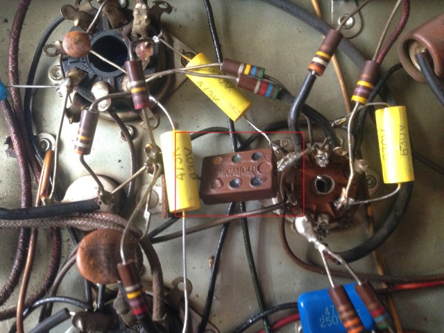
Thanks!
Everything has gone smoothly so far, but looking ahead the caps I'm having a hard time locating are C32-C36. I only see two ceramic caps and I have four.
Also, what is this component? I've never seen one like it before. Resistor? Cap?
Thanks!
-
rvalkenburg
- Senior Member
- Posts: 144
- Joined: Mon Sep 08, 2014 3:53 am
- Location: Cinnaminson, NJ USA
The square cap is C32 it is the 50 mmfd 500 v Mica cap.
C33 was a paper cap, it has both connections to the 12ax7 tube.
C34 is a a small cap connected to the second 6L6 where c29 is connected to and the ground post.
C35 is a small 5 mmfd 1000v ceramic that has both connections to the first 6L6 tube (pins 3 & 5)
C36 you probably do not have unless the amp serial number is below 41280
Ron Valkenburg
-
catboxer
Topic author - Regular Member
- Posts: 53
- Joined: Thu Sep 18, 2014 4:35 am
- Location: Chicago,IL USA
Thanks Ron, I just found the 3 paper caps that threw me off. One was .001 and the other two .005. I had no idea what that square cap was.
-
rvalkenburg
- Senior Member
- Posts: 144
- Joined: Mon Sep 08, 2014 3:53 am
- Location: Cinnaminson, NJ USA
No problem...
I just finished my MRA5 for my 100r last week, I only have to recap c3 (a-d). Just have not traced out which line is what yet, been working on other issues.
I just finished my MRA5 for my 100r last week, I only have to recap c3 (a-d). Just have not traced out which line is what yet, been working on other issues.
Ron Valkenburg
-
catboxer
Topic author - Regular Member
- Posts: 53
- Joined: Thu Sep 18, 2014 4:35 am
- Location: Chicago,IL USA
Haha, tell me about it. I'm saving C3 for last! I wish the values or symbols were on the underside of the cap too. If you figure it out, please share!
I'm thinking of mounting them vertically with the positive leg bent upward and each negative to its own ground on the chassis. Then maybe I'll zip tie them all together.
I'm thinking of mounting them vertically with the positive leg bent upward and each negative to its own ground on the chassis. Then maybe I'll zip tie them all together.
-
Ron Rich
- Forum Moderator
- Posts: 8193
- Joined: Sun May 06, 2007 11:31 pm
- Location: Millbrae (San Francisco area)CA, USA
99% of the time, the "posts" ARE marked--L@@K at em ! Attsa reason for the phunny looking symbols on the side of the can !
On the few that are un-marked, it's simple to follow the wire to another component, and figure out what value it should be--
Ron Rich
On the few that are un-marked, it's simple to follow the wire to another component, and figure out what value it should be--
Ron Rich
-
rvalkenburg
- Senior Member
- Posts: 144
- Joined: Mon Sep 08, 2014 3:53 am
- Location: Cinnaminson, NJ USA
OK I found out how they are labeled... I had to clean the side of C3 to read the printing and then matching the symbols to the very small symbols next to the posts under the amp.
You need to find the D laying on its side, a square a triangle and then nothing, these shapes are cut out around the posts.
The sideways D is 40 mfd 400 V which is C3-D
The Square is 20 mfd 400 V which is C3-C
The Triangle is 20 mfd 350 V which is C3-B
And the one with no symbol is 10 mfd 350 V which is C3-A
I also traced them all out and they match up in the schematic as well. Mine are done and working great.
Ron Valkenburg
-
Ron Rich
- Forum Moderator
- Posts: 8193
- Joined: Sun May 06, 2007 11:31 pm
- Location: Millbrae (San Francisco area)CA, USA
Ron,
Glad you found it-and that it's working !! -not all brands of caps will be marked the same--sometimes even different production runs are marked differently--you MUST look at each cap, to see how it's marked ! Also, if by chance the symbols are printed on the schematic--don't trust them--check for sure, on the cap, itself ! Ron Rich
Glad you found it-and that it's working !! -not all brands of caps will be marked the same--sometimes even different production runs are marked differently--you MUST look at each cap, to see how it's marked ! Also, if by chance the symbols are printed on the schematic--don't trust them--check for sure, on the cap, itself ! Ron Rich
-
catboxer
Topic author - Regular Member
- Posts: 53
- Joined: Thu Sep 18, 2014 4:35 am
- Location: Chicago,IL USA
Thanks! My C3 cap ended up being exactly the same. I was looking for the symbols printed on the bottom of the cap, not thinking they would actually form the shape around the cap leg. Here's how I arranged the 4 caps:
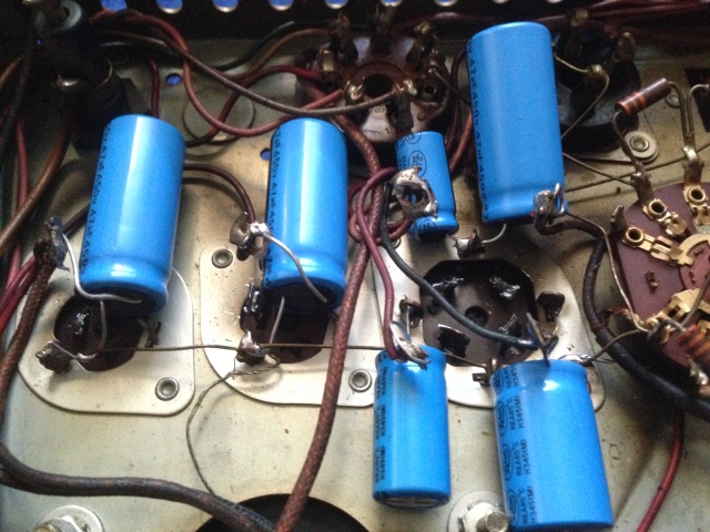
I snipped off the existing legs and soldered those to their respective + leads and then tied each ground into the chassis or the ground braid.
Ron, are you sure C35 goes to 3 and 5 on the first 6L6? I can't tell via the schematic, but mine looks original and going from 3 to 6. You can actually see it pictured above. They also didn't provide me with a 5mmfd cap, instead I have a 10mmfd rated at 1kv. Seems strange that it's 2x the rated mmfd value.
-
rvalkenburg
- Senior Member
- Posts: 144
- Joined: Mon Sep 08, 2014 3:53 am
- Location: Cinnaminson, NJ USA
I am so sorry about that, that was a typo. You are correct, C35 goes from pin 3 to pin 6. I even double checked my schematics and my C35 and it is 3-6.
Ron Valkenburg
Who is online
Users browsing this forum: Baidu [Spider], Yahoo [Bot] and 6 guests
It is currently Thu Oct 06, 2016 1:32 pm