Thanks for this--could you post a schematic/parts list for it ?
This will not work, without modification, ( and may not be needed) on "domestic models", as, neither the Aux power, or the amp power plug socket, is controlled by the on/off switch ( both are always "hot" as long as cord is plugged into a hot outlet---seethe schematics--). Ron Rich

Rowe AMI CD100 -- speaker thump at power on
Q&A about all types of jukeboxes: Wurlitzer, Seeburg, Rock-Ola, AMI, and more.
Okay, diagrams as requested.
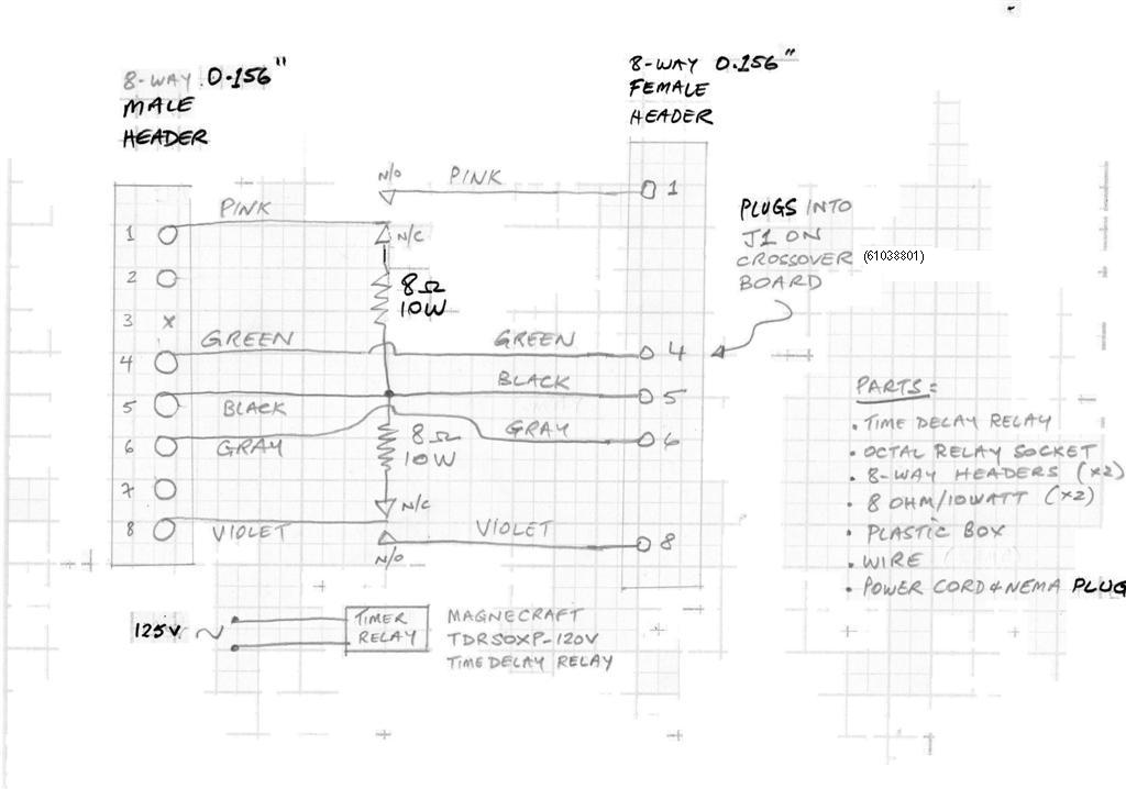
Note that my juke is the first LaserStar model (CD-100) and uses crossover #61038801 (later CD100 models may use a different crossover). This device installs onto J1 of the crossover board, meaning that, should the need arise, the original connection to J1 can be restored quickly and easily.
The octal socket and cement resistors are glued to the base of the plastic box. An opening is cut into the top of the box to accommodate the relay.
Note: I am not 100% convinced of the need for the dummy load resistors, but I included them for good measure so that the amp "sees" a load at power-up until the speakers are switched into circuit at the conclusion of the time delay.
For simplicity and small form factor, I opted for an all-in-1 time delay relay module which has a variable time delay. I opted for 5 seconds. The pin-outs for the time delay relay are as follows. (Pins 2 & 7 are the AC connections.)
Note that my juke is the first LaserStar model (CD-100) and uses crossover #61038801 (later CD100 models may use a different crossover). This device installs onto J1 of the crossover board, meaning that, should the need arise, the original connection to J1 can be restored quickly and easily.
The octal socket and cement resistors are glued to the base of the plastic box. An opening is cut into the top of the box to accommodate the relay.
Note: I am not 100% convinced of the need for the dummy load resistors, but I included them for good measure so that the amp "sees" a load at power-up until the speakers are switched into circuit at the conclusion of the time delay.
- Rowe CD-100 de-thumper schematic (Large).jpg (62.52 KiB) Viewed 181 times
For simplicity and small form factor, I opted for an all-in-1 time delay relay module which has a variable time delay. I opted for 5 seconds. The pin-outs for the time delay relay are as follows. (Pins 2 & 7 are the AC connections.)

- Magnecraft TDRSOXP-120V pins.jpg (89.31 KiB) Viewed 181 times
-
Ron Rich
- Forum Moderator
- Posts: 8193
- Joined: Sun May 06, 2007 11:31 pm
- Location: Millbrae (San Francisco area)CA, USA
Thanks !--BTW, as far as I know, from the mouth of a Rowe factory engineer, "all cross-overs are interchangeable--"
Ron Rich
Ron Rich
Who is online
Users browsing this forum: Bing [Bot] and 6 guests
It is currently Thu Oct 06, 2016 3:34 pm