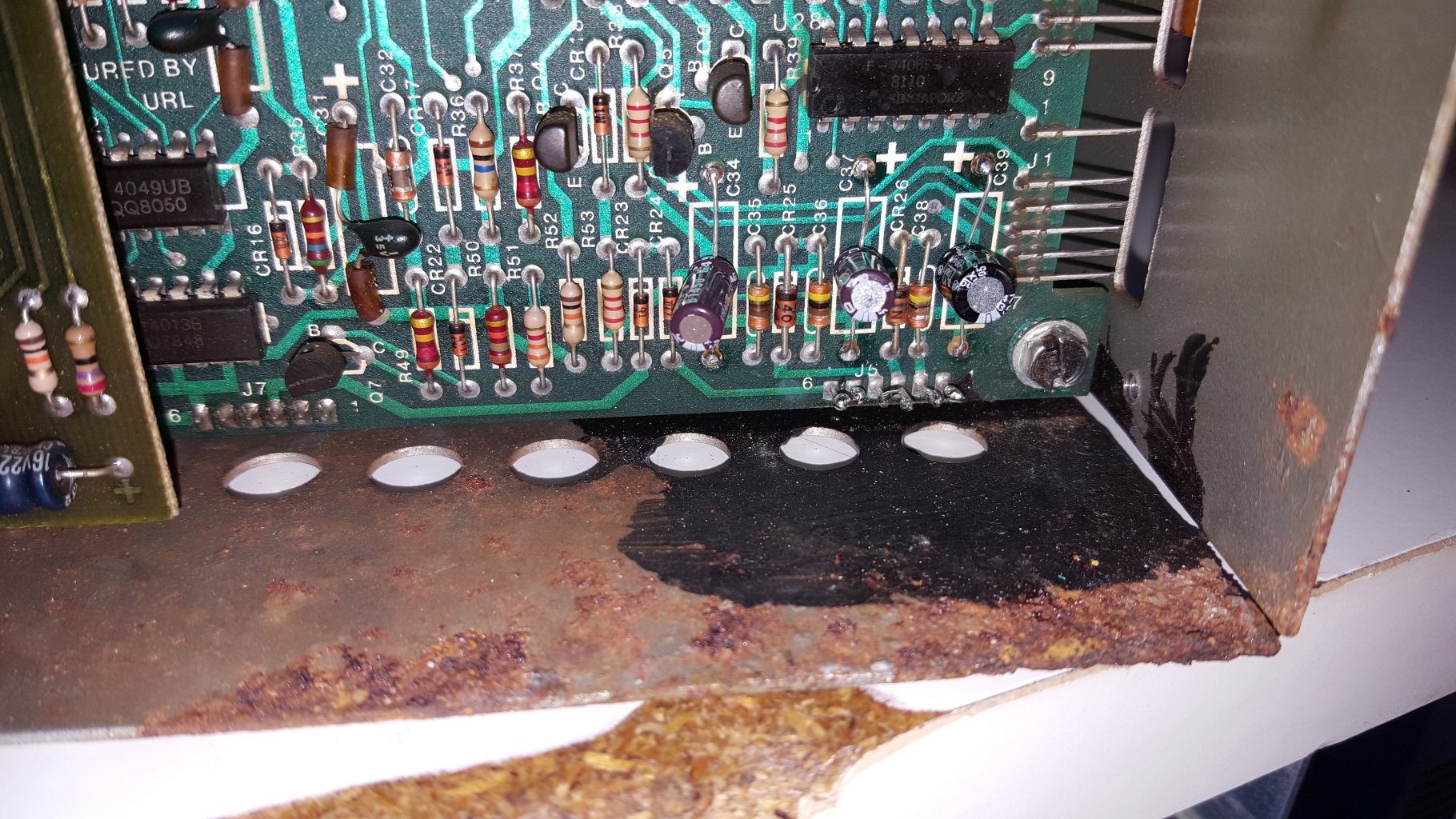
As I had stated in a previous post the MCU had bad battery corrosion previously. To the point that the battery retaining clips had rotted away. The person who worked on this unit previously had repaired the battery connector by soldering the wires directly to the header pins and then covering those with a black silicone to protect it.
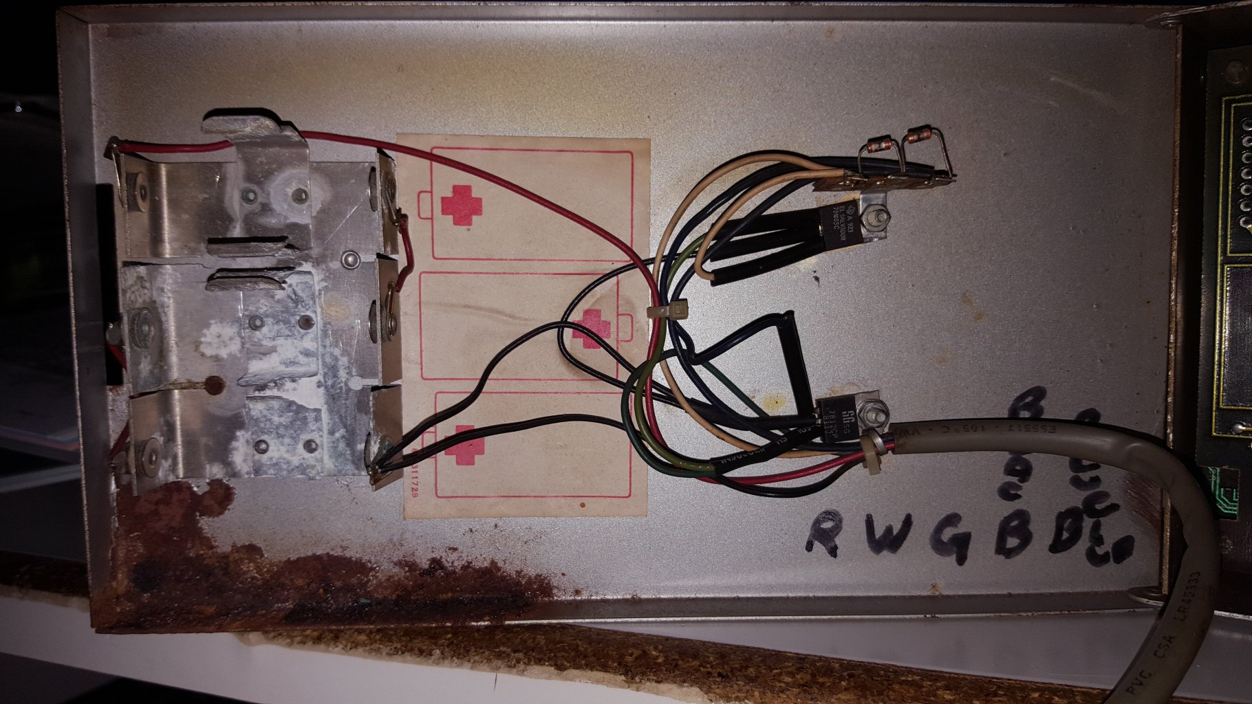
Written in the MCU case was the color coding for how the wires were to be connected. The only problem was that when I clipped the wires to clean the board up and re-solder I didn't realize there are actually 6 pins, not just 5. The current battery cable only has 5 wires, and the header has 6 pins.
Live and learn, I should have taken a picture(s). I have schematics and the books, but the schematics only go as far as the header pins.
The overlay shows connections in the following order from left to right:
+20V
Ground
+12V
+5v
Polarizer
Battery +
I was hoping to see the two transistors and diodes that reside in the battery circuit in the schematic, but they are not shown. Even on the large schematic.
Anyone know which pin I need to skip?