Hi Guys,
I'm working on a 100B with an MRA1-L6 amp. At some point, the amp has been modified with two additional tubes, which I am assuming are some type of AVC circuit. One of the tubes is a 6SJ7, but the second is missing, so I'm not sure what it should be.
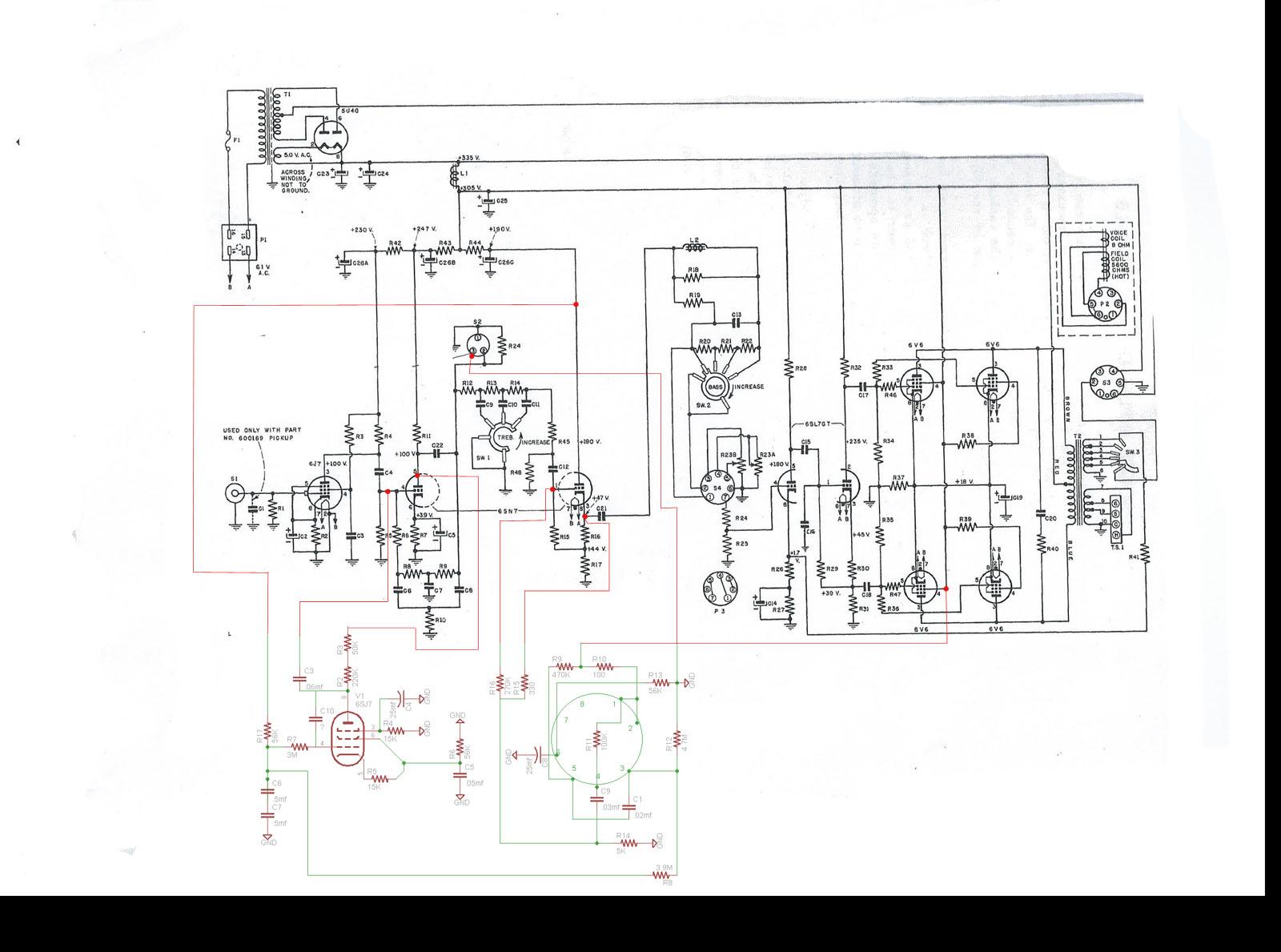
I've attached a schematic of the added components (as best I could see, things are a little crowded), showing the pinout of the missing tube and the connection points to the original circuit. I have a couple questions:
1) Is it worth it to leave these additional components in place, or should I just take everything out and return the amp to it's original configuration?
2) If these additions are worth keeping, does anyone know what the missing tube should be?
I'd appreciate any assistance you guys can provide. Circuit design is a little beyond me.

Seeburg 100B Amp Modifications
Q&A about all types of jukeboxes: Wurlitzer, Seeburg, Rock-Ola, AMI, and more.
-
odog8669
Topic author - Junior Member
- Posts: 14
- Joined: Thu Dec 26, 2013 8:35 pm
- Location: Boston, MA USA
- Attachments
-
- AVC.jpg
- AVC Schematic
- (225.96 KiB) Not downloaded yet
-
Ron Rich
- Forum Moderator
- Posts: 8196
- Joined: Sun May 06, 2007 11:31 pm
- Location: Millbrae (San Francisco area)CA, USA
Hi Odog,
If it's the "snap-in", Seeburg designed AVC upgrade, box, it has three tubes on it--top, L-R
6SK-7--6SL-7. Bottom (center), 6SN-7.
Value--depends--if the "early version", IMHO, not too much--Later version, good.
Also, the mechanism must have the added switch on the top of the upper stack. If this is not there, it will only serve to reduce all volume--quite a bit ! Ron Rich
-
odog8669
Topic author - Junior Member
- Posts: 14
- Joined: Thu Dec 26, 2013 8:35 pm
- Location: Boston, MA USA
Thanks Ron. This isn't a separate box, someone actually added two tube sockets to the amp chassis (where the ID plate usually is) and soldered the components in underneath.
Does anyone have the schematics for the add on box? Maybe it is similar?
Does anyone have the schematics for the add on box? Maybe it is similar?
-
Ron Rich
- Forum Moderator
- Posts: 8196
- Joined: Sun May 06, 2007 11:31 pm
- Location: Millbrae (San Francisco area)CA, USA
I feared that---You might try looking at a MRA-3 schematic ? They are basically the same with the AVC designed into the -3--(different output section). If that's no help, PM me, as I do have the add on schematics, around here--the problem is "where"  ? Ron Rich
Uh-on, there must be someone else like me who does stuff to those old units....and forgets to document it...
Seriously though, this is not big problem, but as you've drawn it the circuit would not work properly due to the absence on a dropping resistor (called R37 -100k-ohm) at the grid 1 of the 6SN7 and the fact that the 6SK7 has no B+ decoupling (it is not directly connected to the plate supply of the 6SN7).
As Ron suggests, review one of the later tube amps that use a 6SK7 as the reactance tube and simply copy that circuit. http://www.verntisdale.com/schem/mra3-l6.jpg
There should be an extra set of contacts at the top of the vertical stack of contacts on the mechanism to squelch the AGC . Since these would have been retrofitted the wires will be outside the mech loom. Seeburg suggested wrapping them in a loose spiral around that cable.
Having AGC on a phono is a real convenience -even at home, so if at all possible, try to set it up properly.
Rob/NYC
"If we believe absurdities, we shall commit atrocities" -- Voltaire
-
odog8669
Topic author - Junior Member
- Posts: 14
- Joined: Thu Dec 26, 2013 8:35 pm
- Location: Boston, MA USA
Thanks Rob. The chances that I missed a connection or two in the schematic I attached are pretty good, things were packed in pretty well and I didn't want to disconnect anything at this point. 
So you think the 6SJ7 currently in place should be a 6SK7, and the missing tube is a 6SL7?
So you think the 6SJ7 currently in place should be a 6SK7, and the missing tube is a 6SL7?
It depends on the actual position in the circuit. As a reactance tube a 6SJ7 would not be suitable as it has a sharp cutoff vs the much longer curve for the 6SK7. I experimented with an SJ7 and it resulted in wild pumping of the gain.
In comparing an MRA-1 to an MRA-3 it appears that the only two tubes are added (6SL7 & 6SK7) so even though AGC is reductive there seems to be enough gain in the original circuit to accommodate it without adding a stage.
What I personally would do is examine the added circuit, compare it to an MRA-3, rebuild it and see how it works.
Rob
"If we believe absurdities, we shall commit atrocities" -- Voltaire
-
odog8669
Topic author - Junior Member
- Posts: 14
- Joined: Thu Dec 26, 2013 8:35 pm
- Location: Boston, MA USA
Thanks Ron and Rich,
I found a schematic for the MRA3 (SN above 14,000) and spent some time today comparing the AVC section to what I have in the MRA1. I attached a revised schematic, redrawn to show the 6SL7 instead of an empty socket, and laid out like the Seeburg schematic is. The only real differences I see are that R58 (all numbers here are off the MRA3 schematic) is not there, the value of R59 is .1M instead of .27M, and C19 and C23 are both 25 mfd. In addition, C28 is .03 mfd instead of .02mfd. I'll change these out when as I rebuild the amp.
The other major difference is that there is no switch and associated resistors to adjust the AVC level. If I can find the space, I think I'll add a rotary switch and the necessary resistors, unless you guys think that is a bad idea.
I did get a little nervous when I didn't see the added squelch switch, but it turns out it was there from the factory. The mech on this must have been switched out with a newer model at some point.
Thanks again for all your help guys. I'll let you know how I make out once it is done.
- Attachments
-
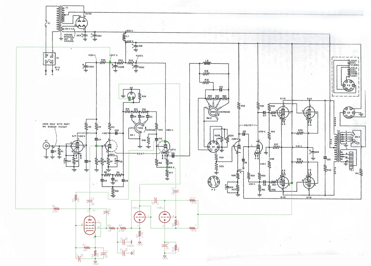
- AVC Schematic
- NewAVC.jpg (185.62 KiB) Viewed 1472 times
You did a nice job w/drawing.
Right away there are still a few problem areas.
1) there -has to be- a resistor between C4 (amp) and the connection from the reactance tube(SK7). The tube functions as a voltage controlled resistor and is part of a divider at that point.
2) On the AGC add-on C4 & C5 are way too small. the proper value is a single 1mfd. I reduced this to .47 to speed up the agc but that is as far as I'd go. This is a simple single-ended design and if the DC voltages change too rapidly it will cause a "thump" and excess cone excursion as well as pump the audio.
3) I'd skip the AGC switch. Seeburg was "antsy" about introducing a compressor for fear that it would anger the "Hi-Fi" crowd (as if they cared about jukeboxes). There is also a situation where an excessively loud record will overdrive the 6SK7 and cause the Grid-1 to go positive and the tube to lose control of the gain. This results in blasting and distortion. Adding that switch allowed one to lower the drive to that section.
If things are properly set up that will not be a problem. I did lower the value of the resistor feeding B+ to G-2 on the SK7. This allowed it to withstand heavier conduction when the G-1 starts to go positive. I did this in 1986 & 1988 and "naturally" kept no notes, I'll have to look at the amps when I'm on that location.
It might be best to emulate the circuit in the HFMA-1 (V-VL) in the AGC section as this area received several revisions over just a couple of years.
What pickup/styli are you planning to use? This will have a large impact on how effective the AGC is.
Rob
"If we believe absurdities, we shall commit atrocities" -- Voltaire
-
odog8669
Topic author - Junior Member
- Posts: 14
- Joined: Thu Dec 26, 2013 8:35 pm
- Location: Boston, MA USA
Thanks Rob.
I just double checked this, and there is no resistor there. The .06 mfd. capacitor is connected directly from pin 8 of the SK7 to pin 4 of the SN7. There is also no resistor there on the schematic for the MRA3, but I can add one if necessary. The HFMA1 schematic shows a 430K resistor, does that seem right?
That's a typo on my part. Those should both be .5 mfd. They've been replaced on the HFMA1 schematic by a single 1 mfd. Since the MRA1 doesn't appear to have the separate chassis and signal grounds present on the MRA3, does it just make sense to put in a single cap here? Should I go with a 1mfd, or would a .47 be better?
On the HFMA1 schematic that resistor is dropped from 56K to 47K. Does that seem about right?
Not really sure yet. Right now it appears to have a Varco ST2X, and from what I have read those aren't very good. Any recommendations? How are the Vern Tisdale cartridges? I'm sure I'll be playing newer stereo records, not original mono 45s.
Rob-NYC wrote:1) there -has to be- a resistor between C4 (amp) and the connection from the reactance tube(SK7). The tube functions as a voltage controlled resistor and is part of a divider at that point.
I just double checked this, and there is no resistor there. The .06 mfd. capacitor is connected directly from pin 8 of the SK7 to pin 4 of the SN7. There is also no resistor there on the schematic for the MRA3, but I can add one if necessary. The HFMA1 schematic shows a 430K resistor, does that seem right?
Rob-NYC wrote:2) On the AGC add-on C4 & C5 are way too small. the proper value is a single 1mfd. I reduced this to .47 to speed up the agc but that is as far as I'd go. This is a simple single-ended design and if the DC voltages change too rapidly it will cause a "thump" and excess cone excursion as well as pump the audio.
That's a typo on my part. Those should both be .5 mfd. They've been replaced on the HFMA1 schematic by a single 1 mfd. Since the MRA1 doesn't appear to have the separate chassis and signal grounds present on the MRA3, does it just make sense to put in a single cap here? Should I go with a 1mfd, or would a .47 be better?
Rob-NYC wrote:3) I'd skip the AGC switch. Seeburg was "antsy" about introducing a compressor for fear that it would anger the "Hi-Fi" crowd (as if they cared about jukeboxes). There is also a situation where an excessively loud record will overdrive the 6SK7 and cause the Grid-1 to go positive and the tube to lose control of the gain. This results in blasting and distortion. Adding that switch allowed one to lower the drive to that section.
If things are properly set up that will not be a problem. I did lower the value of the resistor feeding B+ to G-2 on the SK7. This allowed it to withstand heavier conduction when the G-1 starts to go positive. I did this in 1986 & 1988 and "naturally" kept no notes, I'll have to look at the amps when I'm on that location.
On the HFMA1 schematic that resistor is dropped from 56K to 47K. Does that seem about right?
Rob-NYC wrote:What pickup/styli are you planning to use? This will have a large impact on how effective the AGC is.
Not really sure yet. Right now it appears to have a Varco ST2X, and from what I have read those aren't very good. Any recommendations? How are the Vern Tisdale cartridges? I'm sure I'll be playing newer stereo records, not original mono 45s.
The HFMA1 schematic shows a 430K resistor, does that seem right?
You are looking at the feedback resistor (430K) the added one is R9 (HFMA-1) @100K.
You might at well stay with a single 1MFD. Use chassis ground.Should I go with a 1mfd, or would a .47 be better?
I may have changed that value further, but I'll have to look. Use the HFMA-1 value for now. Unless the input is driven heavily it won't be a problem.On the HFMA1 schematic that resistor is dropped from 56K to 47K. Does that seem about right?
As for carts, there are several choices.
1) Replace the arm assembly with one using the later yellow styli.
2) Use a redhead with one of the new reproduction styli made in Europe.
3) Buy a 345-03D. Expensive and the counterweight must still be cut to balance.
4) Use Tisdale's version. If it balances correctly, this is probably the simplest solution.
!,3 & 4 All use styli that will likely be available far into the future though the cart using the yellow styli will require cutting the plastic on the regular styli to fit the cart.
In all cases the output is likely to be substantially lower than the original cart and thus the AGC action will be less. This can be dealt with but the solution involves adding either another stage of gain at the input, or building a different preamp (I used a 12AX7 on the V-VL amps).
I'd first get the machine working fully and see to what degree the gain difference matters to you.
Rob
"If we believe absurdities, we shall commit atrocities" -- Voltaire
-
odog8669
Topic author - Junior Member
- Posts: 14
- Joined: Thu Dec 26, 2013 8:35 pm
- Location: Boston, MA USA
You are looking at the feedback resistor (430K) the added one is R9 (HFMA-1) @100K.
Yep, you are right. There is a 100K resistor in that location. I also noticed that C4 has been increased to .05 mfd, as it is on the newer model amps with AVC.
Thanks again for all your help. I put in an order today for the new caps, resistors, and tubes I need. I'll let you know how I make out once I'm done rebuilding.
-
odog8669
Topic author - Junior Member
- Posts: 14
- Joined: Thu Dec 26, 2013 8:35 pm
- Location: Boston, MA USA
I just wanted to thank those of you who replied and give a quick update on this. I finally finished replacing the caps and most of the resistors in this amp, and got the new tubes necessary for the AGC. The amp sounds really good, and the AGC is working fine.
When I was rebuilding the amp, I did notice that C20 and R40 (in parallel with the output transformer) had been removed by someone. I put them back in as they should be. Do you guys know of any reason they may have been removed?
I haven't installed a new cartridge yet, but I did build a converter so I can connect an ipod, and I was surprised how nice it sounds.
Thanks again for all your help Rob and Ron. I can post the final schematic with all the changes if anyone is interested.
I'm glad things have worked out.
That R-C on the output plates was there to absorb any kickback transient if the for some reason the speaker is disconnected while driven.
Under such conditions an electrical spike approx ten times the peak audio can be sent back to the tube plates and transformer primary.
Another use for this sort of thing is as a sort of "final filter" to remove vestiges of harmonic distortion.
The problems these schemes cause is that they often affect the audible range (probably not a factor here). Another potential problem is that if the tubes are radically unbalanced the B+ at the plate of one will be a lot different from the other. if a typical paper capacitor cap is used here leakage can result and burn up the resistor.
I generally remove them.
Rob
"If we believe absurdities, we shall commit atrocities" -- Voltaire
Who is online
Users browsing this forum: No registered users and 7 guests
It is currently Fri Oct 07, 2016 12:46 am