Hi everyone.
I was hoping that any of you have wiring schematics on how to wire up the Master Remote Volume control MRVC-2 .
I have a Seeburg KD200 that I purchased a master remote volume control for and it suppose to connect to a 9 pin
dummy plug. I have the 9 pin dummy plug where you unplug your normal volume control, and wire up the remote to the 9 pins.
Number 1-9. it came with 7 feet of wire, and the remote is suppose to be tested and working.
The colors of the 5 wires are white and black red brown and green. I traced the white and black, and connected them to record eject button.
The eject button works fine.
I'm left with red brown and green , to connect to the dummy plug. I need to know if all 5 wires get connected to the dummy plug, and which pin numbers they connect to.
Any help from any of you is greatly appreciated
Regards
Frank.

How to wire up a Seeburg master volume control MRVC-2
Q&A about all types of jukeboxes: Wurlitzer, Seeburg, Rock-Ola, AMI, and more.
10 posts
• Page 1 of 1
-
frankromita58
Topic author - Junior Member
- Posts: 6
- Joined: Tue Dec 15, 2015 9:56 pm
- Location: Toronto
How to wire up a Seeburg master volume control MRVC-2
by frankromita58 » Thu Dec 17, 2015 1:54 am
-
Ron Rich
- Forum Moderator
- Posts: 8194
- Joined: Sun May 06, 2007 11:31 pm
- Location: Millbrae (San Francisco area)CA, USA
Re: How to wire up a Seeburg master volume control MRVC-2
by Ron Rich » Thu Dec 17, 2015 2:04 am
Hi Frank,
You can do one of the following three things-- 1. Look in the service manual. 2. Look at the VC that is now connected, and trace the wires ( I would dis-regard colors !), Or, 3. Axk the seller how to wire it. Ron Rich
You can do one of the following three things-- 1. Look in the service manual. 2. Look at the VC that is now connected, and trace the wires ( I would dis-regard colors !), Or, 3. Axk the seller how to wire it. Ron Rich
Re: How to wire up a Seeburg master volume control MRVC-2
by Rob-NYC » Thu Dec 17, 2015 7:08 am
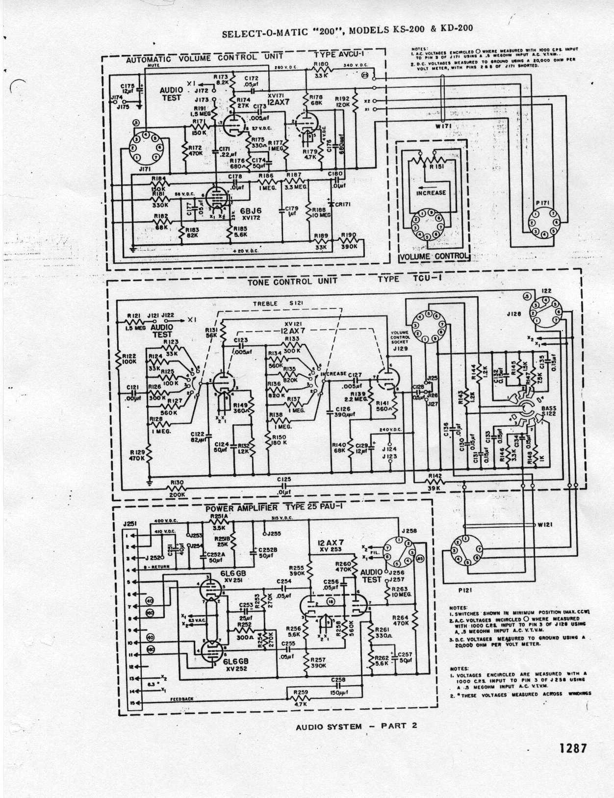
Ok Frank, here are the connections:
http://www.verntisdale.com/schem/kd-200.jpg
Inside the dotted line is the volume control module.
Pin:
1-Pot high side.
2 N.C.
3 High side loudness tap
4 N.C.
5 Low side loudness tap.
6 N.C.
7 Control arm.
8 N.C.
9 Ground end of pot -this is the extreme counter-clockwise position.
--The are as viewed from the solder connection side of the plug NOT the pin side.
- Use shielded cable with stranded wires -not solid.
Rob-NYC
"If we believe absurdities, we shall commit atrocities" -- Voltaire
-
frankromita58
Topic author - Junior Member
- Posts: 6
- Joined: Tue Dec 15, 2015 9:56 pm
- Location: Toronto
Re: How to wire up a Seeburg master volume control MRVC-2
by frankromita58 » Thu Dec 17, 2015 3:35 pm
Rob-NYC wrote:Ok Frank, here are the connections:
http://www.verntisdale.com/schem/kd-200.jpg
Inside the dotted line is the volume control module.
Pin:
1-Pot high side.
2 N.C.
3 High side loudness tap
4 N.C.
5 Low side loudness tap.
6 N.C.
7 Control arm.
8 N.C.
9 Ground end of pot -this is the extreme counter-clockwise position.
--The are as viewed from the solder connection side of the plug NOT the pin side.
- Use shielded cable with stranded wires -not solid.
Rob-NYC
-
frankromita58
Topic author - Junior Member
- Posts: 6
- Joined: Tue Dec 15, 2015 9:56 pm
- Location: Toronto
Re: How to wire up a Seeburg master volume control MRVC-2
by frankromita58 » Thu Dec 17, 2015 3:42 pm
Thanks alot Rob for the great information on how to wire the remote volume control.
I will follow your instruction and give you a follow up later.
At least I got something to work with.
I confident that the information you sent me will work.
Thanks again Rob-NYC
Regards
Frank
I will follow your instruction and give you a follow up later.
At least I got something to work with.
I confident that the information you sent me will work.
Thanks again Rob-NYC
Regards
Frank
-
frankromita58
Topic author - Junior Member
- Posts: 6
- Joined: Tue Dec 15, 2015 9:56 pm
- Location: Toronto
Re: How to wire up a Seeburg master volume control MRVC-2
by frankromita58 » Thu Dec 17, 2015 5:07 pm
frankromita58 wrote:Thanks alot Rob for the great information on how to wire the remote volume control.
I will follow your instruction and give you a follow up later.
At least I got something to work with.
I confident that the information you sent me will work.
Thanks again Rob-NYC
Regards
Frank
-
frankromita58
Topic author - Junior Member
- Posts: 6
- Joined: Tue Dec 15, 2015 9:56 pm
- Location: Toronto
Re: How to wire up a Seeburg master volume control MRVC-2
by frankromita58 » Thu Dec 17, 2015 5:19 pm
Hi Rob
One quick question there 5 wires from the remote volume control.
white black green brown and red. Do these color wires have to be on the right pin numbers.
When I tried to hook it up the toggle switch increase the volume only when you push it up and hold it in the
up position, when I release it , the volume drops.
How many wires connect to the 9 pin dummy?
Could this be due to the connection. Do the white and black wires connect only to the reject button, and also to the 9 pins?
Any help would be greatly appreciated.
Regards
Frank.
Re: How to wire up a Seeburg master volume control MRVC-2
by Rob-NYC » Thu Dec 17, 2015 7:25 pm
One quick question there 5 wires from the remote volume control.
white black green brown and red. Do these color wires have to be on the right pin numbers.
When I tried to hook it up the toggle switch increase the volume only when you push it up and hold it in the up position, when I release it , the volume drops.
How many wires connect to the 9 pin dummy?
Hold-on a minute here Frank, an MRVC-2 is a remote where the audio from the jukebox goes through it.
A PRVC-x is what uses a toggle switch to raise and lower level. There is no "dummy plug" -wires are connected to screw terminals..
This is what an MRVC-x looks like (see original listing):
http://www.ebay.com/itm/161602924569
The colors don't matter, however the wires inside the shield are used for the audio and any outside are for the reject.
Rob
"If we believe absurdities, we shall commit atrocities" -- Voltaire
-
frankromita58
Topic author - Junior Member
- Posts: 6
- Joined: Tue Dec 15, 2015 9:56 pm
- Location: Toronto
Re: How to wire up a Seeburg master volume control MRVC-2
by frankromita58 » Thu Dec 17, 2015 8:07 pm
Hi Rob
Really thanks for the update, I guess l got the wrong remote volume control. I have the one with toggle switch, l guess there's no way to made due the one with the toggle to work, or will It even work on my KD200.
I would have to purchase the one you sent me the link for the
MRVC- 2
Let me know if you think I can make the toggle switch work.
Thanks again Rob-NYC
Regards
Frank
Re: How to wire up a Seeburg master volume control MRVC-2
by Rob-NYC » Thu Dec 17, 2015 8:25 pm
Frank, there is no practical way to make that type work.
Other than buying one on E-pay, you could just buy the volume control itself with a newly manufactured one:
http://www.verntisdale.com/Seeburgpage.htm -and put it into the shell -they are the same. This is the route I would suggest, used pots may be defective anyway.A shielded cord of whatever length will be needed too.
Rob.
"If we believe absurdities, we shall commit atrocities" -- Voltaire
10 posts
• Page 1 of 1
Who is online
Users browsing this forum: No registered users and 9 guests
It is currently Thu Oct 06, 2016 5:01 pm
- Delete all board cookies
- All times are UTC+02:00