Hello,
I'm new to the forum, so please excuse me if I don't get all the procedures correct!
I'm repairing an extremely "got-at" Continental 2 for a friend. To give you some idea how bad it was...
The amplifier chassis had been completely stripped, chassis painted (including where the earth points should be!) and all the components replaced back in some sort of seemingly random order!!
It was then given to an "expert" to fix, this proved as disaster; & then finally on to me. I have over 50 years experience in broadcast & Audio engineering, with a well equipped workshop.
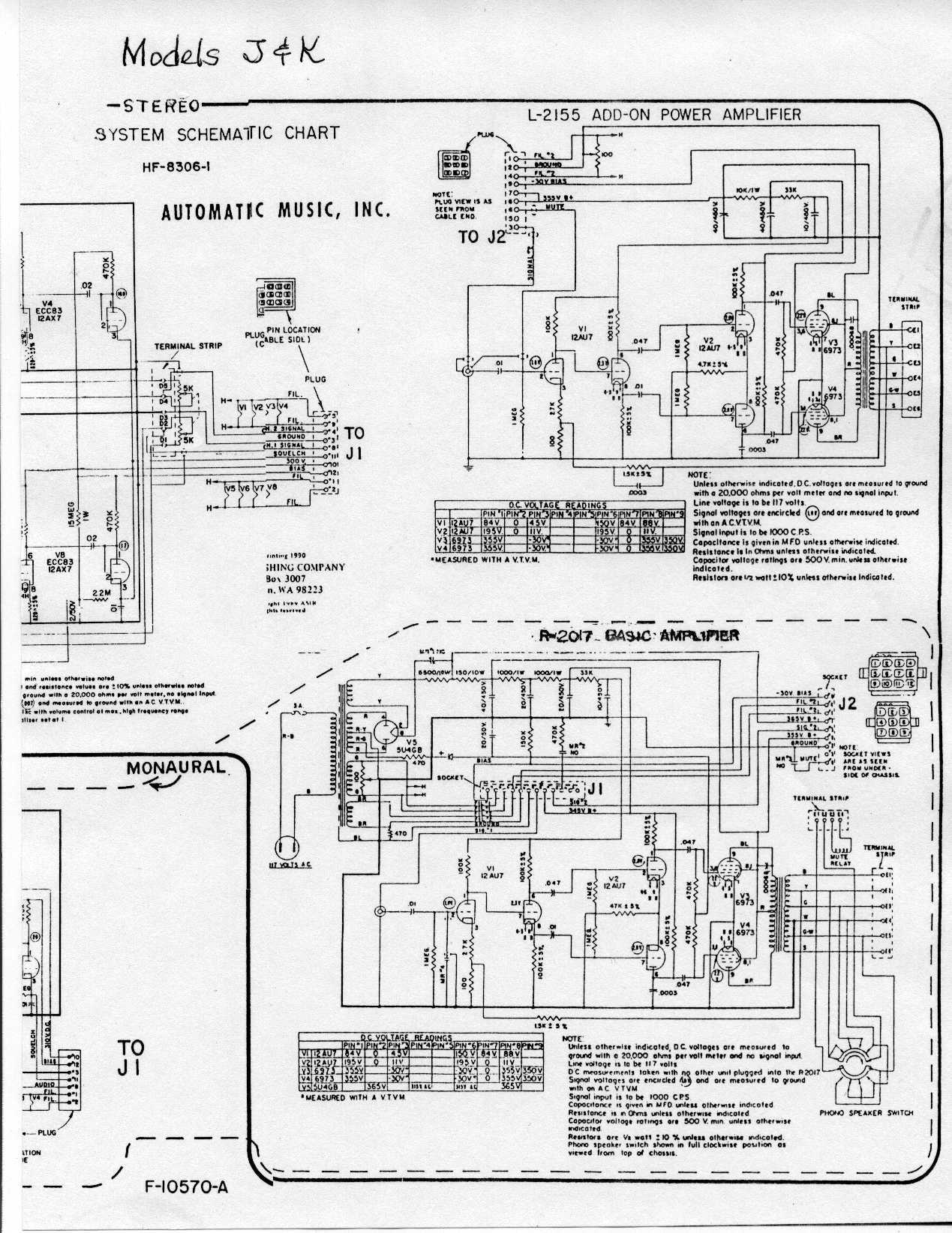
I have the full manual, the amplifier is the R-2017, with a L-2165A control unit.
I have almost re-built both units, but as the original botcher cut all the leads from the output transformer, and also from the phono speaker selector switch, I am missing some information that would not normally be required.
First question: Nowhere in the manual does it show which tappings on the o/p transformer go to the internal 15-ohm speaker & tweeter. Does anyone have these details please?
Question two: Because the output transformer secondary leads have lost their colors it is very laborious trying to sort them out.
Does anyone have a note of the D.C. resistance readings, say taken from terminal E1 to E6 respectively?
Given that information, I can then sort out the switch also.
Any help appreciated.
Thanks,
Dave.

AMI Continental 2 amplifier info
Q&A about all types of jukeboxes: Wurlitzer, Seeburg, Rock-Ola, AMI, and more.
10 posts
• Page 1 of 1
-
Ancient Engineer
Topic author - Junior Member
- Posts: 8
- Joined: Mon Nov 19, 2012 9:08 pm
AMI Continental 2 amplifier info
by Ancient Engineer » Mon Nov 19, 2012 9:29 pm
Re: AMI Continental 2 amplifier info
by Rob-NYC » Mon Nov 19, 2012 9:57 pm
Dave, try looking at the "K" model here:
http://www.verntisdale.com/schem/ami-j-k.jpg -Scroll down to the "basic amp". Since the speakers and OT are the same, that should help.
As for tracing, my procedure is to first establish the primary. the feed a low voltage AC of around 14 volts into it and then measure the potential at the various secondary leads. Once I find the leads with the greatest difference I can then up the AC to an average output tube RMS for this sort of amp, measure the voltages into a specific load(s) and go from there.
You are right, this sort of thing is arduous.
Hopefully, the diagram will eliminate the need for more elaborate methods.
Rob/NYC
"If we believe absurdities, we shall commit atrocities" -- Voltaire
-
Ancient Engineer
Topic author - Junior Member
- Posts: 8
- Joined: Mon Nov 19, 2012 9:08 pm
Re: AMI Continental 2 amplifier info
by Ancient Engineer » Tue Nov 20, 2012 12:17 pm
Hi Rob,
Thanks so much for your reply, I will look at the link that you sent right now.
I used a similar method to you for sorting out the secondary taps, but the results were inconclusive. Because the schematic doesn't show, for example which is the 70v line tap, or where exactly the NFB is in relation to the low-z outputs, it gets as you say, more arduous.
I have it working, after a fashion, but with low output.
Cranking up the input level produces asymmetric clipping & crossover distortion, - all dependent on the secondary loading.
Thanks again, I let you know the final results!
Dave.
-
Ancient Engineer
Topic author - Junior Member
- Posts: 8
- Joined: Mon Nov 19, 2012 9:08 pm
Re: AMI Continental 2 amplifier info
by Ancient Engineer » Wed Nov 21, 2012 6:53 pm
Looks like I've solved the problem although not yet fixed it.
Using an audio generator, & sorting out which lead was which, produced confusing results.
I'd already noticed the asymmetric clipping, which was occurring at quite low output level, so I carried out a couple of checks;
One measuring the inductance of both halves on the primary. This was interesting, one half produced 62 mH, the other only 9 mH.
I then "rang" the two halves using the X - output from a 'scope. Slightly inconclusive, but one half was more damped than the other, not surprisingly, as of course they are on the same core.
I then measured the maximum output before clipping, which was a measly 0.75W into what I had deduced was the 15-ohm secondary winding.
I managed to find an electrically similar output transformer, - not good enough to use, but with nearly the right Ra.
I temporarily substituted that, and was immediately rewarded with 23W into 15-ohms.
That'll teach me not to just take the D.C. resistance of the two primary halves as being any indication of condition!
They both read 106 ohms, but obviously there's a shorted turn or two in there somewhere.
As if I needed further proof, I now note that one of the previous experts had already changed the grid-coupling capacitor to one of the output valves, the one with the dodgy inductance as it's anode load. Obviously then went into grid-current & overheated the one half of the primary.
All very frustrating, a complete re-build from scratch, instead of trying to fix all the previous errors, would have been easier.
So, all I need now is an output transformer, plus tracing the very poor frequency response of the control unit!
I suspect that some of the capacitors in the tone equalizer circuit have been replaced with the wrong values...
Still I have one nice trophy; the last "repairer" had taken out every component, and in doing so , had cleaned some of them, not the switches, which were very corroded, but the main smoothing cap has been treated to the full 'wire-brush in-an-electric drill' process.
It's covered in score-marks, very shiny, & totally open-circuit!
Moral of the story; don't take on repairs from a friend who says 'This won't take you long"
Dave.
Re: AMI Continental 2 amplifier info
by Rob-NYC » Thu Nov 22, 2012 11:39 am
Dave, well you've nailed the problem.
On the plus side -all- of the stereo juke makers used the 6973 from late 1958 'till various times in the first half of the 60's so there should be a lot of options, most makers used 16 ohm speakers as well so only the wattage taps would matter.
That tran was probably killed by a shorted tube. In 1988 as the last of the operators were being driven from NYC by high rents, I inherited a van of parts which included a box of about 14 transformers. Two were for Wurlitzer, the others were Seeburg. Like you, I first measured the primaries and pitched those with radically asymmetric windings on the primaries. None were exactly equal -but I kept those that were close -so I thought. Two years later I'm rebuilding a Seeburg 6L6 based amp and used it as test jig for what I thought were the good trans. Only three passed.
Seeburgs are somewhat notorious for weak OT's, I have not seen this problem in Rowe/AMI, but in those older amps none had any protection from grid shorts. Their 7868 amps had the 100 ohm resistor added after the first year or so of production because that tube is also Hi-mu and thus prone to G2-G1 shorts. My N and O models each had a burned resistor due to that problem. better to change a resistor then a tran. I've suggested adding a 100 ohm -1/2 watt to each G2 pin on any tube amp. Some PA makers (RCA, DuKane) also add approx 10-22 ohm 1 or 2 watt to each plate connection.
In addition to the bad winding the extreme low output you noticed might be due in-part to putting a 16 ohm load on the 70v windings.
Anyway, good luck with it, keep us informed.
Rob
"If we believe absurdities, we shall commit atrocities" -- Voltaire
-
Ancient Engineer
Topic author - Junior Member
- Posts: 8
- Joined: Mon Nov 19, 2012 9:08 pm
Re: AMI Continental 2 amplifier info
by Ancient Engineer » Thu Nov 22, 2012 12:38 pm
Thanks Rob,
I appreciate the extra information. Interestingly, the Rowe versions had amplifiers of U.K. origin, but this Continental 2 is an all U.S. made unit.
Having checked the internet for a likely replacement transformer, I will probably not go for a 'used' one.
I note that Hammond in the U.S. have an almost exact replacement, with the option of ultra-linear taps, so I may go for that.
The only downside is that with transportation, duty, and (in the U.K) V.A.T. all added on, it becomes a very expensive transformer!
In the mean time I will finish off the control unit, & track down the frequency response problem.
I've already re-built the RIAA e.q. onto a piece of perf-board. The original was missing; I assume they were some sort of potted module?
Likewise someone had already removed the capacitor network for the frequency range switch, and replaced it with a jungle of ceramic caps with unidentifiable markings. They don't read correctly, so they'll be the next to go.
Well, it's back to the bench now, to a DVD recorder, that's just displaying "Goobye"
I'm supposed to be retired, but somehow I don't think it will ever happen.
Dave.
Re: AMI Continental 2 amplifier info
by ami-man » Thu Nov 22, 2012 12:45 pm
Hello Dave,
Have you got some specs on the transformer or the number off of the top of the transformer.
If you let me know I will check out what I have got that may be suitable.
Regards
Alan
Alan Hood
ami-man
UK
alan-hood@datex.co.uk
Have you got some specs on the transformer or the number off of the top of the transformer.
If you let me know I will check out what I have got that may be suitable.
Regards
Alan
Alan Hood
ami-man
UK
alan-hood@datex.co.uk
-
Ancient Engineer
Topic author - Junior Member
- Posts: 8
- Joined: Mon Nov 19, 2012 9:08 pm
Re: AMI Continental 2 amplifier info
by Ancient Engineer » Fri Nov 23, 2012 1:00 pm
Thanks Alan,
The manufacturer's ref. number on the Tx is L-2729.
The only spec I have, is that which is shown on the original Ami manual, not a lot! Obviously it needs to match the anode (plate!) load spec of the 6973. Alternatively I suppose one could do what was done in the U.K. & use EL84's.
It doesn't actually say what the secondary taps are, there's obviously a 15-ohm and a 70v output.
There's also the point at which the NFB is taken off, but the diagram does note state any of the individual winding's impedance.
Measuring with a bridge on my faulty transformer is not satisfactory, due to the partial shorted turns on the primary.
It actually looks like a Hammond, and there are certainly Hammond variants that would both physically fit and be as near as possible to the original. They also have the option of UL taps...
Dave.
Re: AMI Continental 2 amplifier info
by Rob-NYC » Fri Nov 23, 2012 8:46 pm
Dave, I don't have a lot of old data on the AMI's but from all the later models using 7868's they tap the NFB from what would be the 24 watt/8 ohm taps (E1-E4) even though all internal speakers are 16 ohm.
Typically I've found 15-22 db of FB in juke amps and since AMI just uses a resistor and doesn't do tone shaping in the FB components, I'd just go with the 8 ohm taps. You can also measure how much gain reduction is occurring with-without FB and see if that seems about right. Any modern tran you get is likely to be better than those old ones (Seeburgs were down 7 db@12khz w/Fb removed) so the amount of feedback isn't going to be that critical.
The two packaged circuits in the preamp are pretty straight forward. On the "treble range" I removed on lead into the package because it put an R/C in the circuit even in the "full" position. I don't have notes as to how much this improved the treble response, but it must have been worthwhile.
On the package between the first two stages, I installed a pot from Pin 6 of the ECC83 (12AX7) and the input of the package. This allowed me to dial-down the amount of FB and improve the treble to compensate for the somewhat dull cabinet speakers. Normally, i would have added an efficient round horn tweeter, but the space and to work in the speaker enclosure (and laziness on my part) made me skip that.
These machine are fine with bass. They have a fairly 'fat" sound with the boost being mostly acoustic and around 70-75Hz.
Rob
"If we believe absurdities, we shall commit atrocities" -- Voltaire
-
Ancient Engineer
Topic author - Junior Member
- Posts: 8
- Joined: Mon Nov 19, 2012 9:08 pm
Re: AMI Continental 2 amplifier info
by Ancient Engineer » Sat Nov 24, 2012 12:13 pm
Rob,
Thanks very much for the info on the feedback cct,on the main amp, & also regarding the tone correction in the control unit.
I must admit I was thinking of modifying the tone correction anyway, as I found before that some Jukeboxes used in home surroundings (i.e. with small rooms) do need some tweaking to give enough bass in particular. This model I'm working on does claim to compensate for Fletcher-Munson effect at low volume settings.
The Continental does therefore seem to have sufficient bass, at least from the power amp, at present. I did measure the frequency response of the power amp on its own, & it was well within spec; flat, or nearly, between 20Hz to 30k, well into the bat range! This was even with the faulty transformer. I was quite surprised at the quality.
Interestingly, the version I have, does have extra tone shaping components in the power amp FB circuit, & they are original. in fact they are one of the few components that the two previous dabblers had left intact! My unit has also been fitted with a horn tweeter & high-level crossover, again, as original.
It's the pre-amp/ control unit that I need to correct, so will look at doing something similar to that which you have described. Currently, it has "telephone" bandwidth; around 200Hz to 2,500Hz, after that, all is lost!
I really appreciate your help & info on this,
Dave.
10 posts
• Page 1 of 1
Who is online
Users browsing this forum: Baidu [Spider], Juke-rocks, NYJB and 5 guests
It is currently Thu Oct 06, 2016 4:05 pm
- Delete all board cookies
- All times are UTC+02:00