
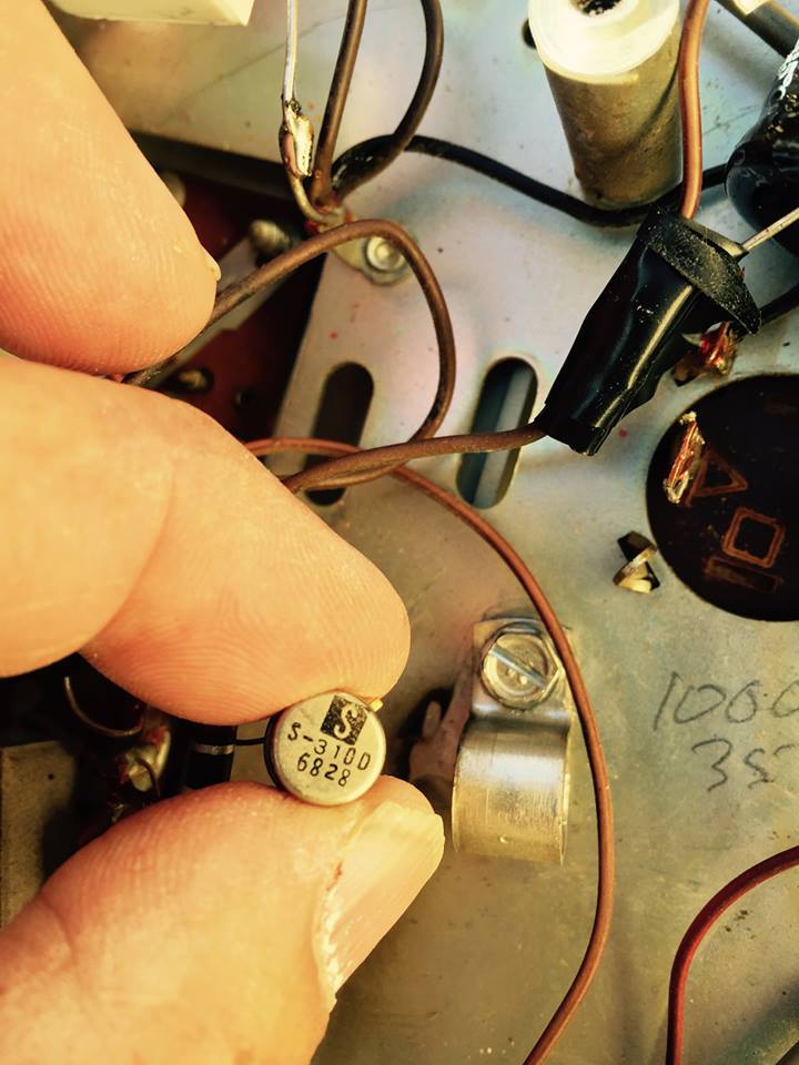
Source for this transistor
Q&A about all types of jukeboxes: Wurlitzer, Seeburg, Rock-Ola, AMI, and more.
-
eddie
Topic author - Senior Member
- Posts: 118
- Joined: Tue Dec 30, 2014 8:03 pm
- Location: Sharon SC USA
-
Ron Rich
- Forum Moderator
- Posts: 8196
- Joined: Sun May 06, 2007 11:31 pm
- Location: Millbrae (San Francisco area)CA, USA
Ed,
What's it used in ?? Didja look it up in the NTE book ?
Ron Rich
What's it used in ?? Didja look it up in the NTE book ?
Ron Rich
-
eddie
Topic author - Senior Member
- Posts: 118
- Joined: Tue Dec 30, 2014 8:03 pm
- Location: Sharon SC USA
AMI MM2
Eddie, if you are still around, that is just an NPN in a TO-5 case with a insulation sleeve. Used both there are v-reg for the preamp card and as a pre-driver on the driver boards (Q-72). When I got two of those amps for commercial service in 1990 that reg was open in one, I just used an NPN power tab (TO-220) booted the tab w/PVC, and used heatsink compound and placed it under the clamp. The power transistor was so overrated for the purposed that it really didn't need any sinking.
I found an old post that I wrote for someone a few years ago concerning that amp series:
--------------------------------------------------------------------------------------------
2N4348 Is a correct replacement in all finals. It is actually just a
higher voltage/power version of the 2N3055 Rowe used in it's original
"100Watt" -MM1 amp.
The entire driver/final amp stages are direct coupled and the voltages
you noted are, from memory, correct -or close enough. If any transistors
shorted or opened that entire chain would would blow the fuse.
So, at this point I'd recommend attention paid to replacing all the
electrolytic caps in the preamp.
Aside from caps the primary area of trouble is the edge connector.
Frankly, the original drawing on this thing is a mess. The are several
omitted connections that would render the circuit useless and at least
two wrong part numbers -these don't matter since the values are the same
L&R so you can just compare.
The principle complaint I had when I used one of these commercially was
thermal stability. After several weeks the finals would begin to idle
too hot and I had to do numerous changes (thankfully simple) to tame
this section before it destroyed itself.
Rowe unlike Seeburg did at least fuse these two stages so that when the
finals failed it didn't cause a meltdown...But really...
Try running them w/no input for several hours and see if the heatsink
begins to get a little too warm. Slight warmth -OK but not hot. This
cam be done in the machine or with nothing connected on a bench.
My print shows a number of mods that I did and unfortunately I didn't
annotate what all of them meant.
Essentially, the trouble begins when Q72 goes into mild thermal
elevation due to normal P-N junction heating from being driven and
probably thermal hysteresis from being heated-cooled in cycles.
According to what I seem to have written(!) R78 (R&L) a 56K/ohm
resistor can be raised in value to lower the initial forward bias on Q72
and this will alleviate some or all of the problem. The danger here is
simply that lowering the forward bias at this stage can produce
crossover distortion, but I don't recall this being a problem.
Some resistor vales are given at 5% tolerance and care should be taken
to keep to that.
There are other more radical steps i seem to have taken but without find
notes I'm not going to recommend them.
I'll try to figure what else I had done in the power section, but
basically, if it doesn't get toasty I'd leave it alone at this stage.
Get the preamp going with audio at Pins 3 & 16 on the pre's edge
connector and the output should work.
--------------------------------------------------------------------------------------
Suffice to say that this isn't my favorite amp design. Rowe. like most other manufacturers was having some of the same problems all the other consumer manufacturers were having. The lack of adjustable bias was a major flaw in a direct coupled power circuit.
Rob/NYC
"If we believe absurdities, we shall commit atrocities" -- Voltaire
Eddie, you don't need a compound for this sort of thing. Just a simple NPN will do:
http://www.onsemi.com/pub_link/Collateral/BD135-D.PDF
Just make sure the collector -emitter voltage is above the B+. In this case the BD139G would be in the ballpark If you have a Radio shack open nearby, they may still have what i used.
Check the 24Volt Zener too.
Rob
http://www.onsemi.com/pub_link/Collateral/BD135-D.PDF
Just make sure the collector -emitter voltage is above the B+. In this case the BD139G would be in the ballpark If you have a Radio shack open nearby, they may still have what i used.
Check the 24Volt Zener too.
Rob
"If we believe absurdities, we shall commit atrocities" -- Voltaire
Who is online
Users browsing this forum: Bing [Bot], Google Adsense [Bot] and 9 guests
It is currently Thu Oct 06, 2016 9:45 pm