I just picked up a decent SS160, ( my 1st box ) I tracked down a constant buzz or hum to the latch solenoid. It seems the 4 rubber mounting grommets are long gone. This I think caused vibration and in turn broke the lead wires to both the 180 & 100 ohm ceramic resistors. It looks like a previous owner by passed the resistors and direct wired the solenoid.
I'd like to replace the two resistors and 4 grommets back to the original set up.
Can any one sketch me out or send a picture as to how the wiring should look including these two ceramic resistors. Since they have rewired it, Its hard to tell how it should be wired correctly.
Thanks in advance, Paul577

SS160 LATCH SOLENOID WIRING HELP
Q&A about all types of jukeboxes: Wurlitzer, Seeburg, Rock-Ola, AMI, and more.
-
Ron Rich
- Forum Moderator
- Posts: 8196
- Joined: Sun May 06, 2007 11:31 pm
- Location: Millbrae (San Francisco area)CA, USA
Paul,
That info is covered in the service and parts manuals issued by Seeburg--see above "announcement-- where to buy--"
if you do no have a copy--
Ron Rich
That info is covered in the service and parts manuals issued by Seeburg--see above "announcement-- where to buy--"
if you do no have a copy--
Ron Rich
Thanks Ron for the fast reply. This seems to be my only issue at this time so I was not sure about spending the money on service & parts manual just yet. But I'm sure down the road they would be handy to have. I'm in the aviation parts business and I know the value of good manuals. I'm also really not sure this will be the unit I keep as I may trade up pretty soon. It did come with the original User manual. Its been a great tool too.
Paul
Paul
-
Ron Rich
- Forum Moderator
- Posts: 8196
- Joined: Sun May 06, 2007 11:31 pm
- Location: Millbrae (San Francisco area)CA, USA
Paul,
The 180 ohm resistor supplies for the "select" lamp--the 100 ohm is in series with the solenoid, to limit power. If "bypassed", it will cause the solenoid to catch fire ( which they are prone to do even with the resistor in circuit---especially if the phono has been modified for "free play"). Ron Rich
The 180 ohm resistor supplies for the "select" lamp--the 100 ohm is in series with the solenoid, to limit power. If "bypassed", it will cause the solenoid to catch fire ( which they are prone to do even with the resistor in circuit---especially if the phono has been modified for "free play"). Ron Rich
Ron, Thank-you So it sounds like the 100 ohm is the one I should be most worried about then. My ss160 is still takes coins to play. I'm okay with that and will leave it that way after what you just told me. But I do notice the solenoid is under power anytime the unit is on and gets hot.
Can you just tell me where the two leads of the 100 ohm connect. I located a direct replacement ceramic resistor at a local old school TV repair shop today. Based on the solder conections I see on the two solenoid tabs, it looks like each resistor lead went to each tab. Sort of across the tabs in other words. Does that sound correct to you ?
The old 100 ohm resistor was still in the clip yet the leads were missing and snipped off any previous conecting points.
best regards
Paul
-
Ron Rich
- Forum Moderator
- Posts: 8196
- Joined: Sun May 06, 2007 11:31 pm
- Location: Millbrae (San Francisco area)CA, USA
Paul,
If the solenoid stays energized, the phono is set on "Free Play"--apparently I mis-spoke--the 100 is soldered across both terminals on the solenoid. Ron Rich
If the solenoid stays energized, the phono is set on "Free Play"--apparently I mis-spoke--the 100 is soldered across both terminals on the solenoid. Ron Rich
-
MarkHitz
- Regular Member
- Posts: 40
- Joined: Sun Apr 22, 2012 3:00 pm
- Location: Dallas Fort Worth Metroplex, USA
I have a Seeburg LS2 which is a couple years newer. The rubber grommets just wear out and there is no exact replacement that I could find. I bought an assortment pack of grommets from Harbor Freight but none are correct IF you are trying to reinsert that metal bushing back inside the rubber part. I did a lot of exaco knife whittling of grommets to get them to fit.
There are people on the Yahoo Seeburg group who own ss160 jukes and perhaps one of them has pics. You should join.
Regarding your comment about obtaining SS160 manuals down the road - If you are just attempting to get it working enough just to sell it / flip it - then I understand what you are saying. If you actually want to keep this as a reliable working jukebox for your enjoyment then having and reading the manuals is essential not optional. Seeburg sold the copyright to Victory Glass so you can get a complete legal manual from them or a bootleg off ebay. You also will need to obtain Ron Rich's helpful Seeburg Mech Guide at some point as your SS160 Select-o-matic Mechanism probably needs some TLC.
Hope this helps.
Ron,
Just what I needed to know- Thanks It seems I'm stuck in the middle on the free play issue. The solenoid is energized 100% when the machine is on, yet you must drop quarters in the slot to get 3 plays ? Like hundreds of machines out there that you have seen who knows what the previous owner(s) have done regarding free play wiring. I'll need to figure that out ASAP. I'd be fine with it back to 100% coin op and knowing that the solenoid is only heating up when its needed. Where is the best place to get info on "freeplay set up" ? Is it in a factory Seeburg manual someplace or was it bypass private owners came up with.
Mark,
Yes I was dealing with the same. I had some rubber grommets here at work that fit pretty good. I could see problems trying to insert the brass bushing so I left them out for now. I'm sure they won't last to long this way but do feel what I have now is better then what I found as they were all missing. Thanks for your imput and I'll check out the yahoo site you mentioned.
paul
-
Ron Rich
- Forum Moderator
- Posts: 8196
- Joined: Sun May 06, 2007 11:31 pm
- Location: Millbrae (San Francisco area)CA, USA
Hi Paul, Mark,
That jukebox, like all jukes, was designed to MAKE money--not be set on free play !
I have no idea what/how some one has "re-jeggered" it to keep the solenoid hot ( a REALLY BAD idea !), without allowing selections? Gonna need the service manual here---
As for the brass spacers--You absolutely must install them, as they determine the "spacing" of that solenoid, and allow the screws to keep it tight. The rubber grommets, are there simply to absorb "sound". The last time I needed some (quite awhile ago), I located them at "Radio Shack"--also most any GOOD "electronics store" sells them. If you can not find any that will allow the brass spacers to be inserted, you can remove the "ridge" on the spacers, without causing any problems--Seeburg used two suppliers for those spacers--one had the ridges, and the other did not.
One other thing--when installing the new 100 ohm resistor, use flexible (stranded) wire to connect between the resistor and solenoid--that way the resistor will not dis-connect as easily. HTH Ron Rich
Good info and I'll get back into all this tonight. I'll do what it takes to get the spacers back in the grommets and try to track down whats feeding this solenoid. I did notice what looks like a aftermarket ground wire added to the solenoid. I pass a Radio Shack on the way home from work. I've not had much luck with Shack in recent years. They pretty much sell cell phones and RC toys these days. But I'll give them a try. I hope I can make it out and not discuss my current cell phone plan or buy a 96pack of AA batteries. On 2nd thought maybe a RC Monster Truck is what my wife needs for Valentines Day !
-
Ron Rich
- Forum Moderator
- Posts: 8196
- Joined: Sun May 06, 2007 11:31 pm
- Location: Millbrae (San Francisco area)CA, USA
Paul,
Yea--no one likes "Rat Shack" today--the only "saving grace" is the fact that they are close by--AND they no longer insist on a name and address( at one time I used to travel, and would wind up in a RS, on my travels--got so bad I started using "Bond--James Bond-#10 Dowining street, London UK") --that's why I mentioned it as a while ago---
Ron Rich
-
MarkHitz
- Regular Member
- Posts: 40
- Joined: Sun Apr 22, 2012 3:00 pm
- Location: Dallas Fort Worth Metroplex, USA
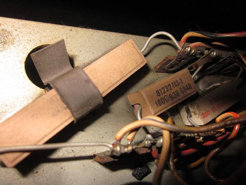
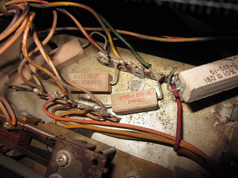
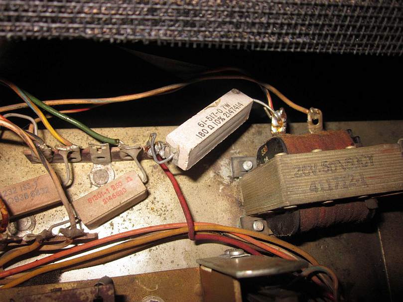
Here is what I see on my LS2 while referring to a LS1 TEC 1613-56 Schematic. Not saying this LS2 is correct – just how it is. Guessing the TEC on your SS160 is about the same as the LS1 / LS2.
Sidebar: Like you, when I obtained my LS2 has the latch solenoid always on and set to free play. However I CANNOT figure out how to revert it back and it is frustrating. Something in the UDPU6 was rigged but I cannot figure out what was altered. But I digress…
There are two 5 lug terminal strips next to each other on the left of the Latch Solenoid. One terminal strip in back and one terminal strip in front.
There is a 100 Ohm 10 Watt Ceramic Resistor (R3402) soldered to the far left lugs of both strips. The two wires coming from the Latch Solenoid (K3401) are also soldered on to these far left terminal strip lugs. Then there are wires from these two going off to plug terminals 2 and 8. So the 100 Ohm 10 W resistor appears to be in parallel with the Solenoid.
The next inner lugs on the left side have a 180 Ohm 5 Watt ceramic resistor soldered between the two strips with yellow/ blue wire coming and orange wire going. I believe this is R3403 and schematic says is to the Album Credit Light.
The middle lugs are riveted to the TES housing.
The next inner lugs on the right side have a 250 Ohm 5 Watt ceramic resistor soldered between the two strips with green wire coming and yellow wire going. I believe this is R3404 which the schematic says is for Steady Light (no clue what a steady light is).
The rightmost lug on the back terminal strip has a 180 Ohm 10 Watt Resistor (R3401) soldered to it and a red wire that goes off per schematic to the Singles Credit Light. The other end of the 180 Ohm resistor is soldered to the left post on the Latch Solenoid.
Interestingly the Schematic shows a fifth resistor, 65 Ohm (R3405) going to a Flasher but there is no resistor (and no clue what would flash).
Sidebar: Like you, when I obtained my LS2 has the latch solenoid always on and set to free play. However I CANNOT figure out how to revert it back and it is frustrating. Something in the UDPU6 was rigged but I cannot figure out what was altered. But I digress…
There are two 5 lug terminal strips next to each other on the left of the Latch Solenoid. One terminal strip in back and one terminal strip in front.
There is a 100 Ohm 10 Watt Ceramic Resistor (R3402) soldered to the far left lugs of both strips. The two wires coming from the Latch Solenoid (K3401) are also soldered on to these far left terminal strip lugs. Then there are wires from these two going off to plug terminals 2 and 8. So the 100 Ohm 10 W resistor appears to be in parallel with the Solenoid.
- TES Resistors C.jpg (55.54 KiB) Viewed 1068 times
The next inner lugs on the left side have a 180 Ohm 5 Watt ceramic resistor soldered between the two strips with yellow/ blue wire coming and orange wire going. I believe this is R3403 and schematic says is to the Album Credit Light.
The middle lugs are riveted to the TES housing.
The next inner lugs on the right side have a 250 Ohm 5 Watt ceramic resistor soldered between the two strips with green wire coming and yellow wire going. I believe this is R3404 which the schematic says is for Steady Light (no clue what a steady light is).
- TES Resistors A.jpg (75.45 KiB) Viewed 1068 times
The rightmost lug on the back terminal strip has a 180 Ohm 10 Watt Resistor (R3401) soldered to it and a red wire that goes off per schematic to the Singles Credit Light. The other end of the 180 Ohm resistor is soldered to the left post on the Latch Solenoid.
- TES Resistors B.jpg (74.74 KiB) Viewed 1068 times
Interestingly the Schematic shows a fifth resistor, 65 Ohm (R3405) going to a Flasher but there is no resistor (and no clue what would flash).
-
Ron Rich
- Forum Moderator
- Posts: 8196
- Joined: Sun May 06, 2007 11:31 pm
- Location: Millbrae (San Francisco area)CA, USA
Mark,
Can't compare---totally different items--- Ron Rich
Can't compare---totally different items--- Ron Rich
Mark,
I want to thank you for taking the time to reply with the pictures. While it may not be my exact unit as Ron states, it still helps me just to see how resistors are installed. I think I also found a couple of your past videos on youtube. Great job on those too.
Paul
I want to thank you for taking the time to reply with the pictures. While it may not be my exact unit as Ron states, it still helps me just to see how resistors are installed. I think I also found a couple of your past videos on youtube. Great job on those too.
Paul
Who is online
Users browsing this forum: Google Adsense [Bot], Yahoo [Bot] and 8 guests
It is currently Thu Oct 06, 2016 11:43 pm