First post!
I'm hoping one of you folks can help me out. The metal reinforcement insert inside the speed control knob on the Collaro Conquest record changer in my '59 Magnavox Symphonette console broke, and the knob does not work without it.
I tried making a new metal reinforcement, but either the metal was too soft or I couldn't get it shaped properly and it popped out.
Any suggestions on how to fix this? Or does anyone have a spare speed they can sell, or have any leads on one? Worst case scenario, I'd be willing to consider buying an entire Conquest, working or not, if the speed knob is intact. Thanks!

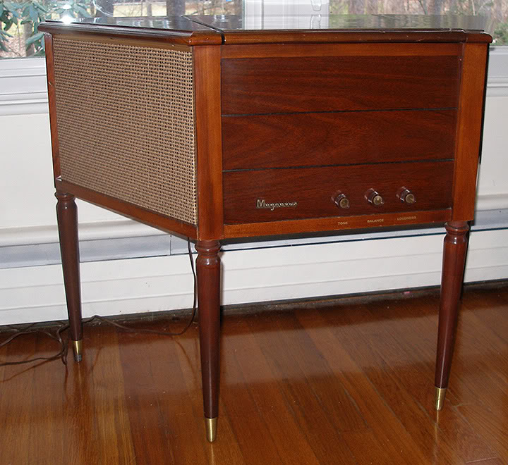
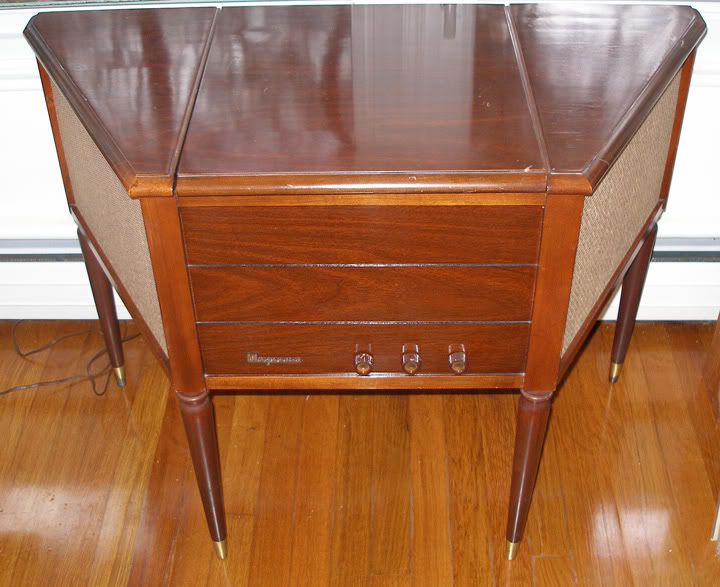
Collaro Conquest & my '59 Magnavox Symphonette console
Electrically amplified phonographs or radio/phonographs and related components (approx. 1928-1990).
-
beatcomber
Topic author - Junior Member
- Posts: 8
- Joined: Thu Mar 12, 2009 11:04 pm
-
 Record-changer
- Senior Member
- Posts: 1139
- Joined: Fri Apr 21, 2006 8:11 pm
- Location: Bloomington IN USA
See your other post.
-
beatcomber
Topic author - Junior Member
- Posts: 8
- Joined: Thu Mar 12, 2009 11:04 pm
I made some from the metal bands used to strap loads onto pallets,
I also made one from the broken one, by making a copper band that goes around the rest of the knob dogs, soldered to the broken parts. I have been running the unit in the avatar this way for 30 years (one broke in 1979, the other in 1982).
Great ideas! What tools did you use to shape the pallet bands? The metal must be very stiff to work.
BTW, your Collaro site is fascinating. I would love to see more details on how you fabricated the mods, ie: converting the tone arm to accept a modern magnetic cart, lowering the tracking weight, etc.
-
beatcomber
Topic author - Junior Member
- Posts: 8
- Joined: Thu Mar 12, 2009 11:04 pm
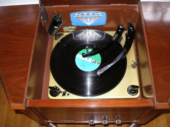
In this image, you can see the metal part that needs to be replaced:

-
beatcomber
Topic author - Junior Member
- Posts: 8
- Joined: Thu Mar 12, 2009 11:04 pm
My wife is a metal artist, and in her studio she has a product called Plastic Steel. It comes in two tubes, which you mix together in equal parts before using. As far as I can tell, it's the same thing as JB Weld, ie: 80% steel, 20% epoxy. My wife cut me off a piece of metal (steel?) with the same dimensions as the broken clip. Using a pair of pliers I shaped it into the approximate shape of the clip and put it on the knob. I filled in the gaps with the Plastic Steel and let it sit overnight.
Voila! I now have a functioning speed selector knob on my Collaro!
Here she is, spinning some Sonny Stitt:
Voila! I now have a functioning speed selector knob on my Collaro!
Here she is, spinning some Sonny Stitt:
-
Record-changer
- Senior Member
- Posts: 1139
- Joined: Fri Apr 21, 2006 8:11 pm
- Location: Bloomington IN USA
beatcomber wrote:I made some from the metal bands used to strap loads onto pallets,
I also made one from the broken one, by making a copper band that goes around the rest of the knob dogs, soldered to the broken parts. I have been running the unit in the avatar this way for 30 years (one broke in 1979, the other in 1982).
Great ideas! What tools did you use to shape the pallet bands? The metal must be very stiff to work.
It is. I used a torch to take the hardness out, bent it to shape, and then used the torch again, quenching it to harden it. It helps to know some blacksmithing.
The other fix was easier:
- Brighten the surfaces of the broken part with a wire wheel
- Tin the surfaces with acid core solder
- With the parts in place on the knob, take two turns of #12 copper wire (I had some extra Romex laying around) around the broken parts
- Lift the parts off the knob, and solder them together.
- Test fit the parts, filing off any excess solder
BTW, your Collaro site is fascinating. I would love to see more details on how you fabricated the mods, ie: converting the tone arm to accept a modern magnetic cart, lowering the tracking weight, etc.
I have done these mods to an original Collaro Custom, and also to a cobra head arm Collaro.
Here is most of what I did.
Parts list:
- Thin washer to fit arm shaft (1/4" ID, I think)
- Thick (1/10 in) washer to fit arm shaft
- Turntable center bearing from Garrard B-series changer
- 1/16" brass rods
- 1/8" OD brass rivets
- 1.25 inch 8-32 brass screw
- 8-32 nut
- 8-32 battery post nut (from dead lantern battery) - Not the one with a plastic knob.
- Solder lugs
- Spring from a click style ballpoint pen
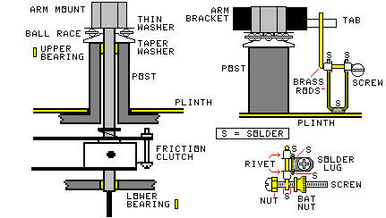
- collaro-mod.jpg (23.77 KiB) Viewed 3834 times
BEARING ASSEMBLY:
- Use a lathe to make the taper washer from the thick washer. (A drill press and a file will do)
- The taper washer is designed to center the turntable bearing around the arm shaft. Make sure the frame of the bearing does not touch the taper washer.
- Smooth the taper washer with #0000 sandpaper while it is spinning on the lathe.
- Put the bearing assembly together and measure its thickness. Subtract the thickness of the Fluon washer that served as the original thrust bearing to get the added thickness of the new bearing.
- Grind that much thickness off the top of the arm post. (This is easier if you remove the change cycle mechanism from the changer). Make sure the top is square. Smooth the top with #0000 sandpaper.
- Use a Dremel tool to very slightly enlarge the holes in the brass upper and lower bearings (yellow in the drawing). I used some of the #0000 sandpaper wrapped around a small mandrill provided with my kit.
- Reassemble the record changer, the arm shaft, and the arm. With the arm clamped to the rest post, adjust the position of the friction clutch so it does not drag, and so the trip finger and arm positioning finger are in the right places. Adjust the arm positioning finger height so it just does not drag on the cam face when the changer is out of cycle.
- Lubricate the ball bearing and the original bearings with a mixture of 50% sewing machine oil and 50% Vaseline, with a little powdered graphite added.
CARTRIDGE MOUNT:
I had to make a special mount to hold the Shure M44 cartridge body in. I cut off the plastic two-hole mount ears from the cartridge, and bonded it to a flat strip of brass I had drilled and tapped to fit the headshell screws (replacing the original mount).
- On the original Conquest, I then fastened a piece of my #12 wire to the upper side of the brass strip, crosswise about half an inch from the font. This allowed me to adjust vertical angle by loosening and tightening the front and back screws.
- For the cobra head arm, I made a similar piece of brass, but with only one hole. I bent it to adjust the angle.
- I replaced the original clips on the tonearm wiring with the ones that came with the cartridge.
COUNTERWEIGHT:
- Remove the original counterweight.
- Drill and tap a hole in the bottom of back end of the existing counterweight.
- Cast an additional counterweight from solder, with a screw that fits the tapped hole. The screw is offset in the counterweight, so I can turn the counterweight to adjust the tracking force. (I could have made it stick out of the back, but then I wouldn't have been able to use the base I already had.)
- Cut the ballpoint pen spring in half, and, put it over the screw before threading the screw into the original counterweight. This keeps the counterweight from changing position.
- Replace the counterweight in the arm. Adjust the new counterweight and the original tracking force spring. This will make the tracking force more consistent over a stack, compared to just using the original spring (because the cartridge is heavier).
ANTISKATING:
I used the same device on both changers, but because the tonearm brackets are different, I had to place them differently.
The original Collaro Conquest has a tab on the right side of the arm mount. The tracking force spring hooks onto it. I made the antiskate device bear on this tab. But I had to hook the tracking force spring into it backwards, so the spring hook stays out of the way of the antiskate. So the antiskate device is mounted straight to the right of the arm on this unit.
The cobra head arm does not have that tab, so I used the arm mounting screw on the front as a tab. So the antiskate device is directly in front of the arm on this unit. Make sure the antiskating device does not hit the head of the screw,
- It is important that the horizontal portion of the brass rod is 3/8 of an inch below the bottom of the tab (or screw). Make all of the other parts with this in mind.
- It is important that the brass rod just loosely fits the inside diameters of the rivets without rattling in them. Make sure the parts you have fit in this way. You can use sleeves if you have them. I used rivets because I had them and they fit.
- Make the brass rod for the actual antiskate crank first. Slip the rivets on the rod, then bend 1/2" at one end to touch the tab. Bend the other end around the screw. Make sure the straight part of the rod goes over the top of the screw.
- Adjust the parts on the antiskating adjustment screw so the screw is slightly heavier on the head end of the screw when the battery nut touches the brass rod. Then remove the battery nut and solder the rod to the screw.
Now make the support from a U-shaped piece of brass and the solder lug.
- Clamp the solder lug under one of the screws holding the change cycle parts to the plinth. These screws are in different locations on different models. Make sure the solder lug is big enough to reach the location of the antiskate unit. You might have to solder two lugs together to make it stiff enough.
- Form a U of brass rod so it touches the solder lug at the bottom, and the rivets at the top. If possible, you can bend the solder lug around the brass rod to hold it. Remember that it must hold the antiskate crank rod horizontal, and at a level 3/8" below the tab or screw.
- Solder the U of brass to the solder lug.
- Solder the brass U to the rivets. Be careful to not get any solder inside the rivets, or it will solder the wrong brass rod to the rivets.
- Rotate the antiskate crank back and forth, to make sure the crank turns freely with a minimum of friction.
- Assemble the unit. The battery nut should point to the rear on the Conquest, and to the right on the cobra head changer. You may have to bend the portion of the brass rod that touches the tab to keep the screw assembly from touching the plinth or the arm, and to keep the rod from touching the arm post.
Adjustment is tricky, because you have no calibrations. I usually do it with a loud bass drum track on a test record I have. It purposely throws the stylus out of the groove if the antiskate is set wrong. I just notice which way it jumps out, and adjust the battery nut.
If your eyes are good,you can notice which way the stylus deflects when the stylus touches the groove. Adjust the antiskate for no deflection.
-
Record-changer
- Senior Member
- Posts: 1139
- Joined: Fri Apr 21, 2006 8:11 pm
- Location: Bloomington IN USA
More:
You can see the bearing, the counterweight, and the antiskate in the photos on this page:
http://geocities.com/midimagic@sbcgloba ... ollaro.htm
The first photo barely shows the bearing, and part of the extra counterweight is visible as a silver object under the back end of the arm.
Note that the brass cylinder behind the arm is a single play 45 spindle I salvaged from another record player, sitting in a socket I made for it in the back of the base. The 45 changer spindle is in the cut-down original holder behind the overarm. They have nothing to do with the counterweight
Also do not mistake the overarm shaft for the counterweight. it is silver too. I turned the overarm post around so the notch is facing the arm. This keeps the overarm from dropping below the spindle ledge, making the last record drop gently. I also removed the circlip from the overarm, so it can be taken off if the changer function is not needed, and during 45 use. It fits in a socket in the back of the base.
The third and fourth photos partly show the antiskate unit. You can also see the end of the extra counterweight sticking out behind the arm.
You can see some of my other modifications in these pictures:
- I modified the rest post so the arm rests closer to the spindle, and adjusted the friction clutch to match. This allows automatic play of 6" records. Note that this did not work with the original cartridge, because a dropping 12" record hit the stylus selector in the microgroove position.
- The cue control is just behind the automatic knob.
- The pitch control is the black knob on the base behind the left side of the changer.
- Although you can't see it from the photo, pushing the play control beyond the play position activates full manual operation with trip defeat. But it must be held in that position. Releasing the control returns the changer to automatic.
- the Autospeed sensor is to the left of the overarm.
- I added the strobe disc (silver with a red center). But it must be removed to use the 45 spindle or to play 4" records.
- I have a set of AudioTex 45 repeat discs, with spiders in the holes. These can be used to repeat a record in the stack. The only requirement is that the next record after that record must be the same size.
- I have a trick for indefinite repeat of a record. I put the record on the turntable, put a rubber grommet around the spindle ledge, and put another record the same size on the spindle ledge and the grommet. The second record never drops, so the changer repeats the record on the turntable.
- The same thing can be done for 45s, by raising the 45 spindle an eighth of an inch after the first record drops. The second record never drops.
Last edited by Record-changer on Sat Mar 28, 2009 10:23 pm, edited 3 times in total.
-
Record-changer
- Senior Member
- Posts: 1139
- Joined: Fri Apr 21, 2006 8:11 pm
- Location: Bloomington IN USA
I just though of another mod you could make while the changer is apart. I cut off half of the width of the friction clutch locator ear to the left to the trip finger, allowing the arm to move closer to the spindle. This allows the changer to play 4" hip pocket records manually. I left enough of the locator ear to keep the arm from touching the spindle.
If you haven't made a full manual mod (harder to do), there is another way to start a 4" record:
- Leave the changer off. Make sure the turntable is not rotating.
- Place the record on the turntable.
- Move the arm as far as it goes toward the spindle.
- Move the arm back out to the edge of the 4" record and place it on the record. Make sure the arm does not move any farther outward.
- Turn on the play control.
The changer should trip at the end of the record.
This trick allows you to place the arm anywhere (except the trip groove of a hip pocket record) and have it not start the change cycle when you start the turntable rotating.
Actually, I know a way to make it play one 4" record automatically, but that takes some doing.
-
beatcomber
Topic author - Junior Member
- Posts: 8
- Joined: Thu Mar 12, 2009 11:04 pm
WOW!!!!!!!!!!!!!!!!!!!!!!!! 
Thank you for taking the time to post all that valuable info!
Thank you for taking the time to post all that valuable info!
-
Record-changer
- Senior Member
- Posts: 1139
- Joined: Fri Apr 21, 2006 8:11 pm
- Location: Bloomington IN USA
I just added more to the posts. Look again.
One thing to remember is that, while these mods increase the usefulness of the changer, they destroy any antique value it might have in the future.
One thing to remember is that, while these mods increase the usefulness of the changer, they destroy any antique value it might have in the future.
-
Record-changer
- Senior Member
- Posts: 1139
- Joined: Fri Apr 21, 2006 8:11 pm
- Location: Bloomington IN USA
My website will be going down in a couple of months.
Yahoo is discontinuing the Geocities site, replacing it with a pay site with fees that only a business can pay.
Yahoo is discontinuing the Geocities site, replacing it with a pay site with fees that only a business can pay.
Who is online
Users browsing this forum: No registered users and 5 guests
It is currently Thu Oct 06, 2016 6:47 pm