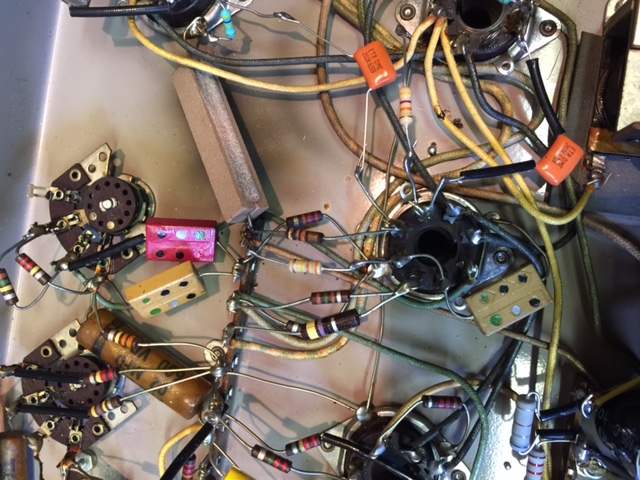
I have a model D hideaway that I wanted to resurrect, just for the fun of it. It's in decent shape so I pulled the amp and started recapping and replacing out of tolerance resistors. When I got to the 6SN7 closest to the output tubes it didn't match the schematic at all. Pin 3 has two resistors coming off of it to two separate wires from the transformer, I'm guessing that they are opposite ends of the same winding as there is little resistance between the wires. I'm not sure if this is factory but it's been like this for a very long time and I'm pretty sure it was working when removed from service as I purchased it from the owner of the restaurant that closed down years ago.
My particular amp is beige colored and most I have seen on the web are black.
Perhaps there was a difference?
Not sure how to proceed, any help, information or suggestions appreciated.
Mauro

AMI Model DD Amplifier Wiring
Q&A about all types of jukeboxes: Wurlitzer, Seeburg, Rock-Ola, AMI, and more.
-
Uptown
Topic author - Junior Member
- Posts: 15
- Joined: Wed Aug 12, 2015 12:21 am
- Location: Mississauga, Ontario, Canada
- Attachments
-
- AMI DD Amp.jpg (156.54 KiB) Viewed 804 times
Mauro, pin 3 is a cathode of the driver section of the driver-paraphase tube. Since it comes from the output tran it is feedback. Either they modded the ckt, or did their usual sloppy drawing. It looks original, I'd leave it.
Rob
Rob
"If we believe absurdities, we shall commit atrocities" -- Voltaire
-
Uptown
Topic author - Junior Member
- Posts: 15
- Joined: Wed Aug 12, 2015 12:21 am
- Location: Mississauga, Ontario, Canada
Hi Rob,
I'm glad you replied.
I don't have enough electronic theory knowledge to understand how this circuit behaves but it looks like a mistake even if it's original. Does it make sense that both sides of a winding end up at the same pin through these 2 resistors?
I was hoping someone might have a similar amp and could look at it.
Anyway I have great confidence in all your answers and will take your advise and leave it, I guess I was just curious about how this feedback circuit worked as opposed to grounding one side of the winding as shown in the schematic.
Thanks for your input,
Mauro
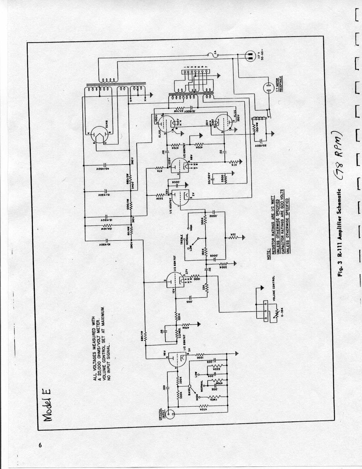
Mauro, take a look at the E (45rpm) amp:
http://www.verntisdale.com/schem/ami-ea.jpg
This makes more sense schematically and looks similar to what you have.
Rob
http://www.verntisdale.com/schem/ami-ea.jpg
This makes more sense schematically and looks similar to what you have.
Rob
Last edited by Rob-NYC on Fri Aug 14, 2015 12:25 pm, edited 1 time in total.
"If we believe absurdities, we shall commit atrocities" -- Voltaire
-
 MattTech
- Senior Member
- Posts: 1461
- Joined: Tue Apr 29, 2008 7:38 am
- Location: Philadelphia Pa USA - Home Electronics - Service Technician
Looks like a standard cathode bypass method with a bit of transformer-fed negative feedback to me.
The Internet is a marvelous thing, however it's not a good substitute for actually being there.
-
Uptown
Topic author - Junior Member
- Posts: 15
- Joined: Wed Aug 12, 2015 12:21 am
- Location: Mississauga, Ontario, Canada
Rob,
That's it!
Thank you for posting that, I feel much better about it now.
Probably a mid-production change that is not reflected on my schematic.
The "not knowing" would have bothered me to no end.
Back to work on this one now.
Many thanks,
Mauro
That's it!
Thank you for posting that, I feel much better about it now.
Probably a mid-production change that is not reflected on my schematic.
The "not knowing" would have bothered me to no end.
Back to work on this one now.
Many thanks,
Mauro
I found the same wiring situation on a DD amp I just recapped. The Model E schematic for the R-105 p is much closer to what I found, not the DD schematic found in the D service manual.
Another question though...
I did find that the volume is pretty low, maybe 1/2 of what I'd expect. Tone quality is good, just low volume. Using a Pfanstiehl P-51, which has worked well on other AMIs I have recapped. I can get it to an acceptable level only if I bump up input signal level to about 2 or more volts with an audio generator. Everything I've checked seems to be to specs; B plus voltage good, tubes check ok and have also been swapped, resistors and caps check good. Any thoughts about what else I can check or do to get more volume? Thanks, Carl.
Carl, the ceramic you selected does have a lower output than the original cart (0.4 vs 1 volt). I would also check that the caps across tube cathodes are good -try jumping additional caps.
Check that the volume control is the correct value, and that the motor relay is original impedance.
Is the speaker original?
Rob/NYC
Check that the volume control is the correct value, and that the motor relay is original impedance.
Is the speaker original?
Rob/NYC
"If we believe absurdities, we shall commit atrocities" -- Voltaire
Rob - thank you so very much for your thoughtful reply.
The volume control is the correct one, 0 to 50K ohms.
The speaker is also original, AMI 16 ohm. I also tried another identical AMI speaker, no change in volume. The TT plate current relay coil is reading 58 ohms; don't know what the specs should be, but I have a working AMI B amp that reads 60 ohms in the equivalent coil.
I am using the P-51 only because I've had good luck in other similar AMI amps, they're readily available, and cheap:) Do you have a suggestion for another cartridge with higher output? Or a modification to make it work better?
Regarding the cathode caps, could you expound on that a bit? To which tubes would you try adding add'l capacitance first, and in what increments? I do have a capacitance substitution box.
Thanks again for any help! Carl.
-
MattTech
- Senior Member
- Posts: 1461
- Joined: Tue Apr 29, 2008 7:38 am
- Location: Philadelphia Pa USA - Home Electronics - Service Technician
In order for that R105 amp to have enough gain for a ceramic, it would need reconfiguring the 6SN7 input and changing the 2nd half from cathode follower to conventional driver, along with standardizing the volume control.
The Internet is a marvelous thing, however it's not a good substitute for actually being there.
Carl, looking at these two schematics:
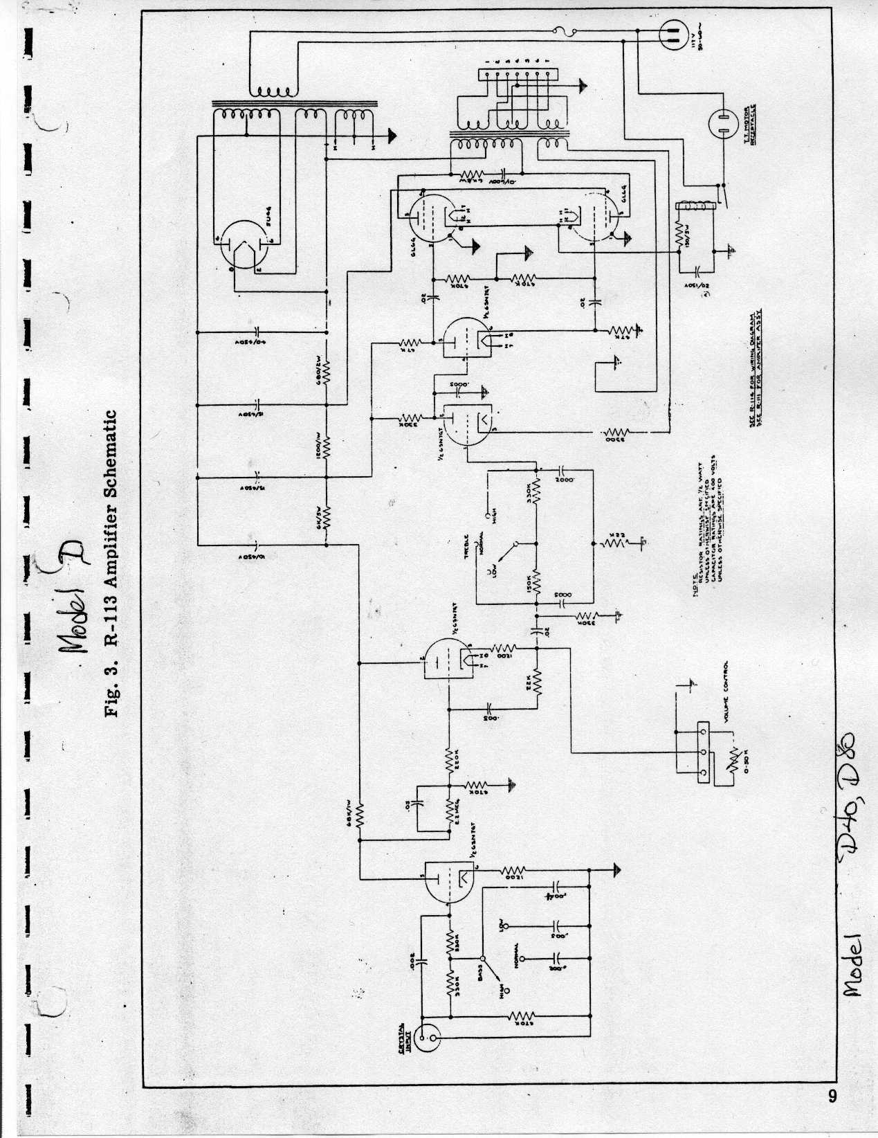
http://www.verntisdale.com/schem/ami-d.jpg:
http://www.verntisdale.com/schem/ami-e.jpg
You can see that the first stage cathode has no bypass cap. Adding one would give approx 6-7db of additional gain. Start with approx 22mfd -but any higher value would be OK since this is not in a feedback loop.
AMI designed these in to two configurations; one for 78s and the other for 45rpm. Since 45 need more gain than 78 (at least back in the early days of 45rpm), AMI simply added cathode bypass caps to make up the difference.
Rob
"If we believe absurdities, we shall commit atrocities" -- Voltaire
It turns out that this (apparently an R105) amp already does have a bypass capacitor at the first 6SN7 cathode. The R105 wiring schematic I found for 45 rpm shows a lead to one of the caps in a multi cap can, but it's now a 22uf since I recapped amp.
I tried adding more capacitance but it made no volume difference at all. Another poster mentioned rewiring the 6SN7 and volume control, but I think that's over my head without specific directions.
Any other thoughts or cartridge recommendations?Thanks again for your time and consideration, Carl.
I tried adding more capacitance but it made no volume difference at all. Another poster mentioned rewiring the 6SN7 and volume control, but I think that's over my head without specific directions.
Any other thoughts or cartridge recommendations?Thanks again for your time and consideration, Carl.
Carl, sorry about the delay in answering you (busy Christmas) Unfortunately, without the amp in front of me it is hard to diagnose this sort of problem when all other parameters seem Ok and I can't check them myself. One subtle problem is that if a plate resistor drifts high it will cause too great a voltage drop across it for a strong tube. However, if that stage's tube is weak it will draw less and the measured voltage can appear withing range. Subbing a known-good tube is the best test here.
Have you tried connecting your meter to the cart input on the amp, using it's a low AC voltage scale and seeing how much comes from the cart?
Another test it to connect a tuner or CD player (the recording outs from a receiver are Ok too). These will typically have a level of 300-500 mv output. See how that compares in level to the cart.
Rob
"If we believe absurdities, we shall commit atrocities" -- Voltaire
Rob - Merry Christmas! ...and thank you for responding.
The plate resistors check out OK. I'm getting about 400-700 mv output from the P-51 cart, which I believe is fine for that cart. Also tried a couple tunes off of my iPhone, which (interestingly) appears to measure at exactly 500mv steady output at max volume through a tone signal generator app I downloaded. Also tried running cart input through a little modern "phono input" amplifier I had picked up on EBay. It normally puts out about 3V. I used a variac to vary the voltage of the output signal by adjusting the voltage to its power supply transformer. I found that I get good volume through the R105 amp with an input signal of about 1.2V or greater.
BTW, I'm in Suffolk Co. on LI. I believe you're in NYC? Do you take amps to work on? I could bring it etc. I'll buy lunch too...
Thanks again, Carl.
Who is online
Users browsing this forum: Google Adsense [Bot] and 9 guests
It is currently Thu Oct 06, 2016 4:58 pm