Hi All,
I have been busy these last months in Classic Car hell. Two engine needed to be torn into so my Jukebox stuff has just had to wait.
************
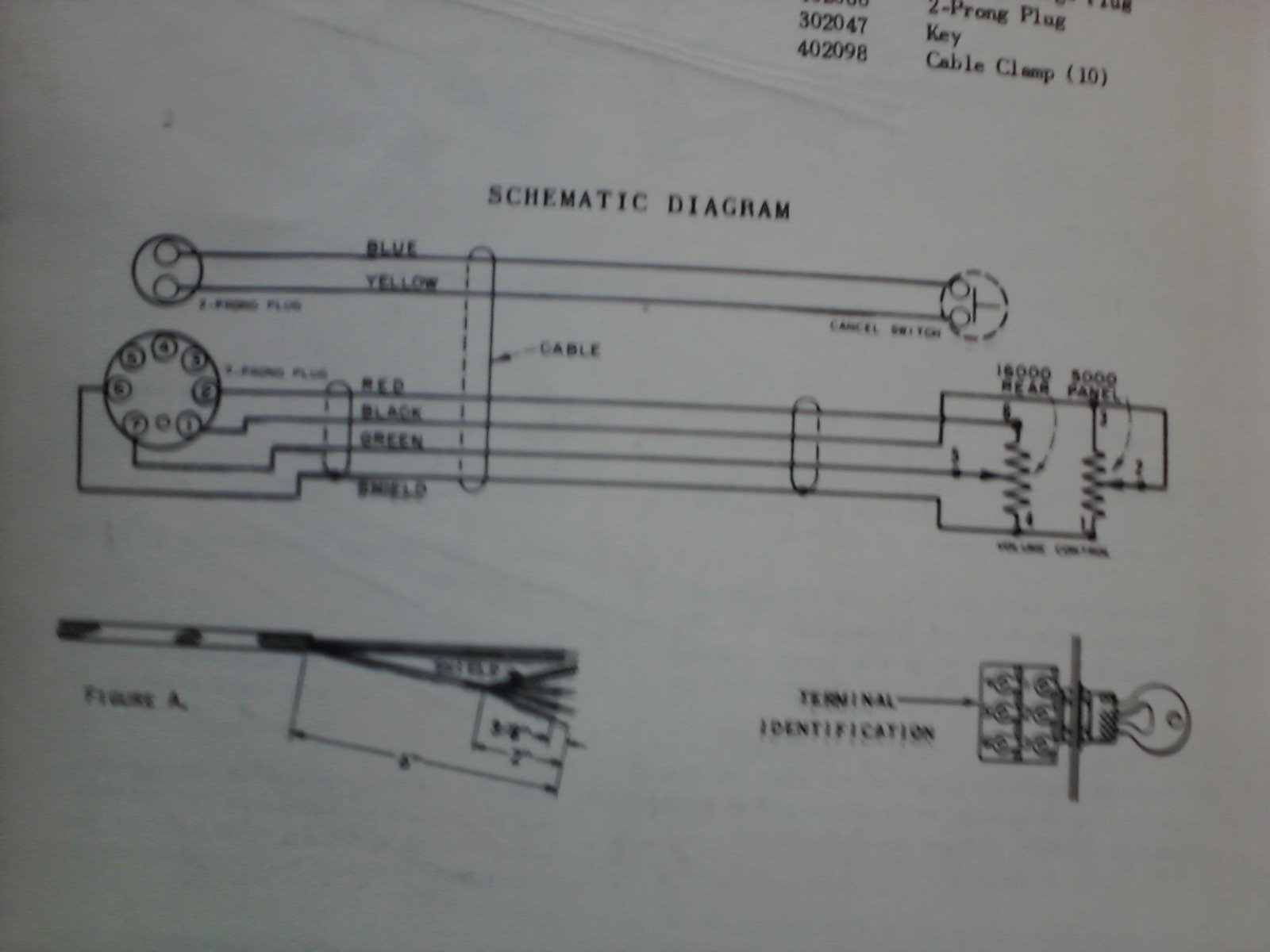
I have found a double gang POT that I have added resistors to so that it is close (5K and 16K) to what the specification is for a M100A Seeburg remote. The problem is that I have no idea if the six contacts are in the same "pattern" as the original. See the attached photo of the page in the manual. The problem is that the contacts are labeled one through six on the POT and the PLUG. I followed the same pattern via the color code, but that may just a guess.
What I want to know is that if anyone has a remote volume control... can you take a VOM and measure the resistance at each plug end with the POT at 12 o'clock and then say at 10 O'clock. That way I should be able to wire the plug correctly and do something that will harm the amp when I pug it in.
Thanks, James

Remote Vol Wiring
Q&A about all types of jukeboxes: Wurlitzer, Seeburg, Rock-Ola, AMI, and more.
-
James_Douglas
Topic author - Regular Member
- Posts: 77
- Joined: Wed May 29, 2013 1:36 am
- Location: San Francisco, CA USA
- Attachments
-
- p_00055.jpg
- (593.67 KiB) Not downloaded yet
-
Ron Rich
- Forum Moderator
- Posts: 8196
- Joined: Sun May 06, 2007 11:31 pm
- Location: Millbrae (San Francisco area)CA, USA
Hi James,
You can do it yourself--simply look at (measure) the volume control on your amp--same part was used for both local and remote functions ( and exact value re-pro's, ARE available at tisdale) Ron Rich
You can do it yourself--simply look at (measure) the volume control on your amp--same part was used for both local and remote functions ( and exact value re-pro's, ARE available at tisdale) Ron Rich
-
James_Douglas
Topic author - Regular Member
- Posts: 77
- Joined: Wed May 29, 2013 1:36 am
- Location: San Francisco, CA USA
Hi Ron,
Tisdale's will not work as I am using a MRVC-2 case with the large round volume control.
I tried it and just about sent the voice coil of the speaker out of the box, through the wall, and down the street!
Obviously, I got something wrong. What I did was to put a resistor in parallel with each pot element until each measures 5K and 16K respectively.
However, something is not working correct and I am getting full volume.
With the POT at 12 O'clock I get:
Shield to Green at 5K
Shield to Red at 5K
Shield to Black at 16.62K
With the POT at 10 O'clock I get:
Shield to Green at 3.4
Shield to Red at 48.36K
Shield to Black at 15.61K
What I have wrong is beyond me. In addition to this little problem...I need to get my Seeburg AP-1 down to you. I think I will dump both of these in your lap...unless you want to make a trip up to The City again.
Best, James
-
Ron Rich
- Forum Moderator
- Posts: 8196
- Joined: Sun May 06, 2007 11:31 pm
- Location: Millbrae (San Francisco area)CA, USA
Hi James,
Do you have page 8005 and 8006 in your Service Manual ? That shows the RVC wiring, which should work with any "case"--and the Tisdale supplied VC.
Either way on the other things, is OK by me--
Ron Rich
Do you have page 8005 and 8006 in your Service Manual ? That shows the RVC wiring, which should work with any "case"--and the Tisdale supplied VC.
Either way on the other things, is OK by me--
Ron Rich
-
James_Douglas
Topic author - Regular Member
- Posts: 77
- Joined: Wed May 29, 2013 1:36 am
- Location: San Francisco, CA USA
Hi Ron,
Well, I think I have an idea what is up. I pulled the rear panel off the box and traced the volume wires to the plug.
Assuming the shaft is to the right and one is looking down onto the POTS...
The 4 wires on the Dual gang POT run as follows:
#1 (front POT) jumps to #4 (rear POT) then runs with a black wire to ground then Pin #6
#2 (front POT) jumps to #3 (front POT) and ALSO runs (Light Gray) to Pin #4
#3 (Front POT) jumps to #2 (front POT)
#4 (rear POT) jumps to #1 (front POT) and (black) goes to a ground and Pin #6
#5 (rear POT) runs (Tan with tracer) to Pin #5
#6 (rear POT) runs (brown) to Pin #3
There is the problem. In the schematic on the last page (152) of the manual I have they show pins 1,2,6, and 7 as being used on the MRVC-1. Also, those were the pins with cut wires on the plug I got from Bill up in Napa.
So the questions is, which one to have faith in? I suspect that I should just duplicate what the main volume control on the box does and ignore the schematic in the book.
Thoughts?
James
PS. For anyone who is interested, I did a resistance check of the factory switch in place and the results are as follows:
When the switch is at the 12 O'clock position lowest volume:
Front POT:
#1 to #2 = 27.4 ohms
#1 to #3 = 27.4 ohms
#2 to #3 = Jumped
Rear POT
#4 to #5 = 15.5 ohms
#4 to #6 = 17.6K ohms
#5 to #6 = 17.5K ohms
When the switch is at 10 O'clock position, most volume:
Front POT:
#1 to #2 = 4.432K ohms
#1 to #3 = 4.432K ohms
#2 to #3 = Jumped
Rear POT
#4 to #5 = 17.5K ohms
#4 to #6 = 17.51K ohms
#5 to #6 = 20.7 ohms
-
Ron Rich
- Forum Moderator
- Posts: 8196
- Joined: Sun May 06, 2007 11:31 pm
- Location: Millbrae (San Francisco area)CA, USA
Follow the example,in the amp--
Ron Rich
Ron Rich
-
James_Douglas
Topic author - Regular Member
- Posts: 77
- Joined: Wed May 29, 2013 1:36 am
- Location: San Francisco, CA USA
Hi Ron,
Followed the lead of the onboard POTS. Double checked the Ohms. Everything is identical.
Howling loud!
I pulled the dummy plug case off, cracked it while I was at it, and note that they jumper #2 to #3 and #1 to #4 and #7 to #5.
I guess I have to head back to the garage and add jumpers to the remote plug to match!
James
-
James_Douglas
Topic author - Regular Member
- Posts: 77
- Joined: Wed May 29, 2013 1:36 am
- Location: San Francisco, CA USA
I added the jumpers like the dummy plug and the remote "sort of" works now.
I would have thought that the remote would completely replace the main volume control. But what I am getting is that I need to have some output via the main volume control or I get nothing when I rotate the remote. If I give the main about a 1/4 turn then I can control the volume with the remote.
This just does not feel correct to me and I am concerned that I could do some damage to the amp.
Can anyone confirm this behavior?
Thanks, James
-
Ron Rich
- Forum Moderator
- Posts: 8196
- Joined: Sun May 06, 2007 11:31 pm
- Location: Millbrae (San Francisco area)CA, USA
James,
Something's wrong here ! To use a "remote", one needs to unplug the volume dummy plug, and plug the remote into that socket--,
This opens all the connections to the "local VC", so it should not affect the volume no mater where it's turned. Ron Rich
Something's wrong here ! To use a "remote", one needs to unplug the volume dummy plug, and plug the remote into that socket--,
This opens all the connections to the "local VC", so it should not affect the volume no mater where it's turned. Ron Rich
-
James_Douglas
Topic author - Regular Member
- Posts: 77
- Joined: Wed May 29, 2013 1:36 am
- Location: San Francisco, CA USA
Ron,
That is what I did. The dummy is out on the table and the plug/cable to the remote is in place.
With the plug (not the dummy) in place it played way too loud. Once I added a set of jumper wires to that plug that were identical to the dummy the thing "sort of worked".
Remember that the master on-board volume control is hard wired to that plug on the under side. With the remote plug in place, with the exact same wire/pin configuration, both are available at the same time. That is the part I do not understand.
Like I said in my above posts, the schematic in the manual shows the MRVC-1 using different pins that what the on-board volume control uses...that's why I think something is wrong...It is like I have to volume controls in series...
James
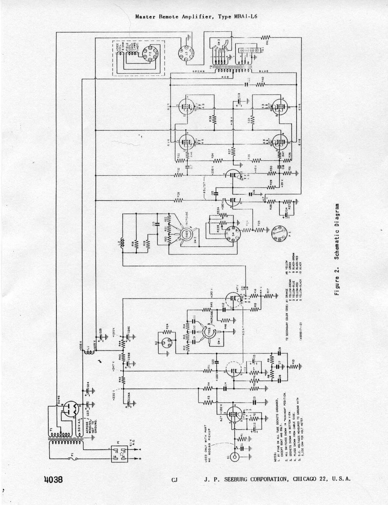
James, based on this schematic: http://www.verntisdale.com/schem/mra1-l6.jpg -and your photo, I suggest this wiring:
Looking at the pot as pictured, the top two sets of lugs, one on each section: Ground connect to Pin 6 RVC plug. --Make sure this is connected properly or you will get full volume w/no control.
The center lugs are the arm (wipers). Arm of the 16K-Ohm pot goes to Pin 7. Arm of the 6K-Ohm pot strapped to the high side lug and both to Pin 1.
High side (bottom lugs in your pic): 16K-Ohm pot to Pin 2.
There should be NO connection to the internal volume pot when RVC is in-use.
Rob-NYC
"If we believe absurdities, we shall commit atrocities" -- Voltaire
-
Ron Rich
- Forum Moderator
- Posts: 8196
- Joined: Sun May 06, 2007 11:31 pm
- Location: Millbrae (San Francisco area)CA, USA
James,
As Rob mentioned--there should be zero connections to the internal volume control, when using a "remote". One of Rob's
"Geppeto friends" must have been "playing around" and hard wired it to the socket--See the schematic for correct socket wiring.
The whole purpose of the "dummy plug" -SOCKET- design is to connect either, an internal, or external, volume control to the amp., quickly, by "changing the plug". Ron Rich
-
James_Douglas
Topic author - Regular Member
- Posts: 77
- Joined: Wed May 29, 2013 1:36 am
- Location: San Francisco, CA USA
I am going to be gone all day...I will post photos of everything tomorrow. The on-board volume control, wiring, and socket is all dead stock. Shows no signs of any work ever done. I suspect that the manual wiring for the remote is correct. That the remote plug uses the other pins and thus "isolates" the original" on-board control. There is probably some other combination that I somehow missing...
Back in 24 hours...
James
Back in 24 hours...
James
-
Ron Rich
- Forum Moderator
- Posts: 8196
- Joined: Sun May 06, 2007 11:31 pm
- Location: Millbrae (San Francisco area)CA, USA
Hi James,
I would bet my "bippy", if I had one, that the wiring is NOT original to that amp !
I have worked on too many of them, and never seen a socket "hard wired" to the VC---
That would defeat the purpose of having a socket-- Seeburg would never have installed it, if they could have just hardwired the VC into the circuit. Ron Rich
-
James_Douglas
Topic author - Regular Member
- Posts: 77
- Joined: Wed May 29, 2013 1:36 am
- Location: San Francisco, CA USA
Hi Ron,
Got back early. I just pulled the attached photo of ebay. Same AMP. You can see the volume control ,the 4 wires running from it , and the 4 wires terminate and are soldered to a socket. The other side of that socket has the dummy plug or the remote volume plug which can be plugged into it.
I suspect we are talking about 2 different things and/or I have screwed up on my descriptions.
James
Got back early. I just pulled the attached photo of ebay. Same AMP. You can see the volume control ,the 4 wires running from it , and the 4 wires terminate and are soldered to a socket. The other side of that socket has the dummy plug or the remote volume plug which can be plugged into it.
I suspect we are talking about 2 different things and/or I have screwed up on my descriptions.
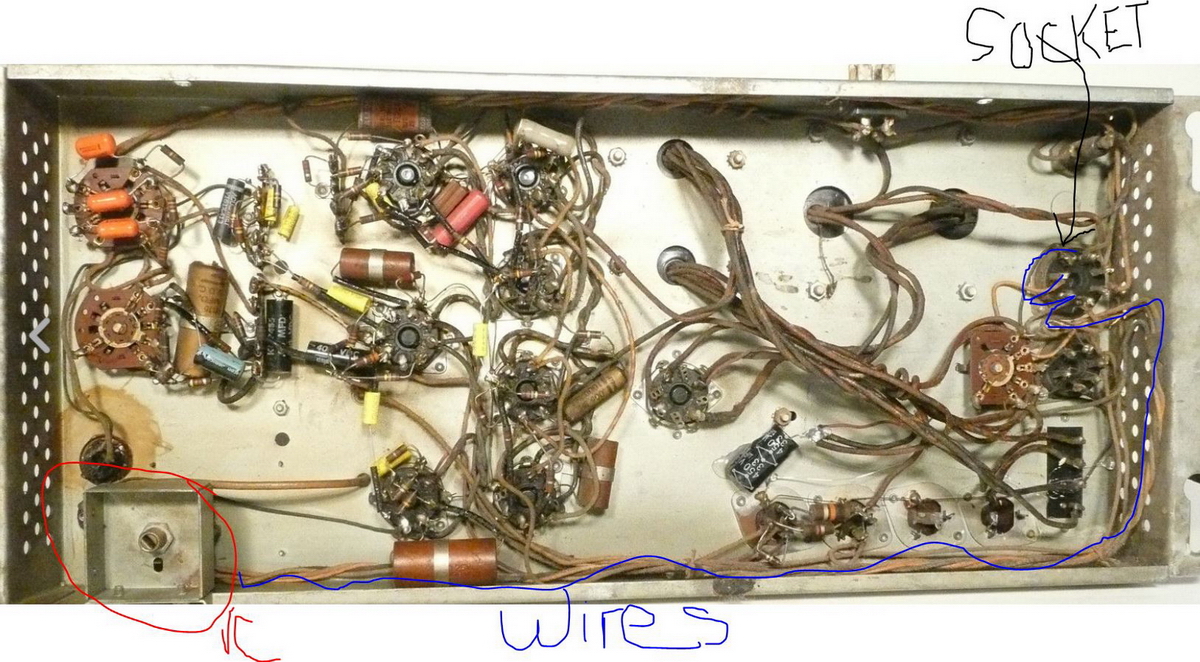
- amp_underside.jpg (670.5 KiB) Viewed 853 times
James
Who is online
Users browsing this forum: No registered users and 8 guests
It is currently Thu Oct 06, 2016 11:53 pm