Hi
This machine has a working 41056-1A tube amplifier for sound anyway. I have cleaned all contacts in the control box, mute realy and play control relay, however i don't have the mute function. There is no mute beofre the start of the record or at the end of the record. Also there is no mute if i scan the record basket, any suggestions. I have measure the resistor around the vincinity of the mute relay and are reading fine
regards
clones

Rockola 434 amplifier 41056-1A
Q&A about all types of jukeboxes: Wurlitzer, Seeburg, Rock-Ola, AMI, and more.
-
clones
Topic author - Senior Member
- Posts: 582
- Joined: Thu Aug 11, 2011 11:29 am
- Location: County Louth, Ireland
Hi
Just an upate on the mute relay problem. Since the amplifier can only be viewed from the back, i removed the amp and i extended a few of the cables and have now the amplifier on a bench beside the jukebox so i can view the operation of the relay. During scan or play the relay is not energising and de-energising, if i maually activate the relay it will mute the sound. I have tried a few other relays but they don't energise. There are two input wires for the relay which originate from the power supply box, voltages on both are -29.5 volts dc using the chassis of the amp as ground. Can anyone point me in the right direction
regards
clones
-
Ron Rich
- Forum Moderator
- Posts: 8196
- Joined: Sun May 06, 2007 11:31 pm
- Location: Millbrae (San Francisco area)CA, USA
Clones,
I am ASSUMING here, as I do not have the schematic--
Most of the time relays are supplied with power on one terminal, and "ground" ("earth" to you") on the other terminal through some type of switch. If you have the schematic, it should show the switched terminal in the amp section. You will then need to follow that wire to the mechanism section, and locate the switch. I would assume that either the switch failed, or it is not connected to ground---
HTH, Ron Rich
-
clones
Topic author - Senior Member
- Posts: 582
- Joined: Thu Aug 11, 2011 11:29 am
- Location: County Louth, Ireland
Thanks Ron, its just the one last nagging issue i have with this machine, i thought it shouldn't be getting voltage on both inputs to the relay. (if anyone had seen this machine a few months ago anybody would have said dump it but with a bit of patience i was able to restore it)
regards
Clones
regards
Clones
-
Ron Rich
- Forum Moderator
- Posts: 8196
- Joined: Sun May 06, 2007 11:31 pm
- Location: Millbrae (San Francisco area)CA, USA
Clones,
You are not "getting voltage to both sides--" What you are reading, is the voltage through the relay coil.
If the coil was open, you would only see a reading on one terminal--
Ron Rich
You are not "getting voltage to both sides--" What you are reading, is the voltage through the relay coil.
If the coil was open, you would only see a reading on one terminal--
Ron Rich
-
clones
Topic author - Senior Member
- Posts: 582
- Joined: Thu Aug 11, 2011 11:29 am
- Location: County Louth, Ireland
Hi
At the moment I have the two inputs for the relay disconnected and measure around -29 vdc on each input, is this correct
regards
clones
At the moment I have the two inputs for the relay disconnected and measure around -29 vdc on each input, is this correct
regards
clones
-
Ron Rich
- Forum Moderator
- Posts: 8196
- Joined: Sun May 06, 2007 11:31 pm
- Location: Millbrae (San Francisco area)CA, USA
Hi Clones,
Not quite sure what you are calling "inputs" ? Please re-word---
Ron Rich
Not quite sure what you are calling "inputs" ? Please re-word---
Ron Rich
-
clones
Topic author - Senior Member
- Posts: 582
- Joined: Thu Aug 11, 2011 11:29 am
- Location: County Louth, Ireland
Hi
what i mean re inputs is the following
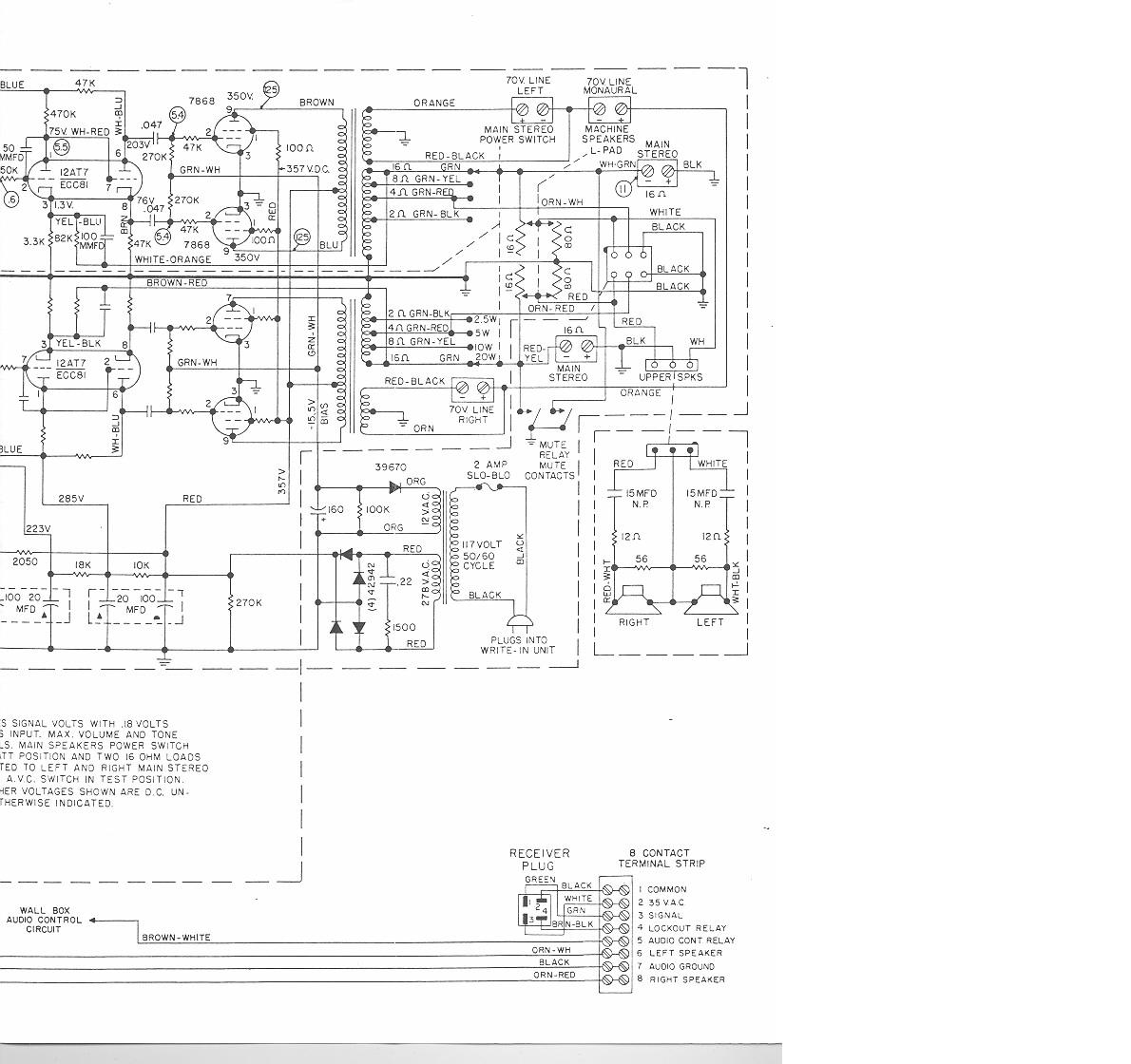
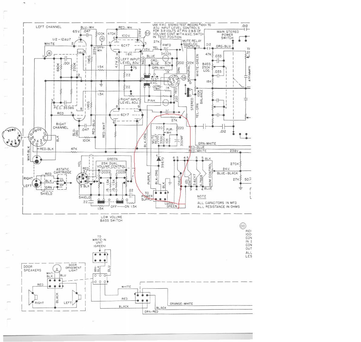
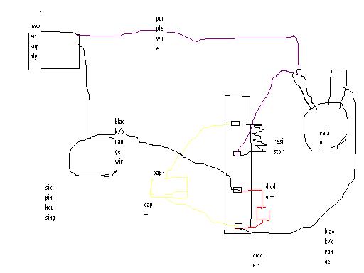
the two wires that will cause the relay to energise, i have attached one half of the amp schematic with the area circled in red and the other half for reference, the purple and black/orange wires coming from the power supply eventually form the starting point to energise the relay. I have replaced the 300uf capacitor at the relay, not sure if i can upload photos but this would show what i am on about
regards
clones
what i mean re inputs is the following
the two wires that will cause the relay to energise, i have attached one half of the amp schematic with the area circled in red and the other half for reference, the purple and black/orange wires coming from the power supply eventually form the starting point to energise the relay. I have replaced the 300uf capacitor at the relay, not sure if i can upload photos but this would show what i am on about
regards
clones
- Attachments
-
- rockola434part2.JPG
- (152.87 KiB) Not downloaded yet
-
- rockola 434.JPG
- (124.15 KiB) Not downloaded yet
-
Ron Rich
- Forum Moderator
- Posts: 8196
- Joined: Sun May 06, 2007 11:31 pm
- Location: Millbrae (San Francisco area)CA, USA
Clones,
From what I see--the wire going to the round socket, pin 5, up-top, second schematic, controls the relay-----is that diode good ??
Where does this plug go--to the mech ? If so, I would think it goes to a switch on the mech that connects to ground when relay should be energized ? Where does the square socket connect to on the power supply ? Ron Rich
-
clones
Topic author - Senior Member
- Posts: 582
- Joined: Thu Aug 11, 2011 11:29 am
- Location: County Louth, Ireland
Ron
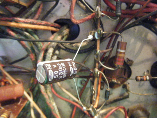
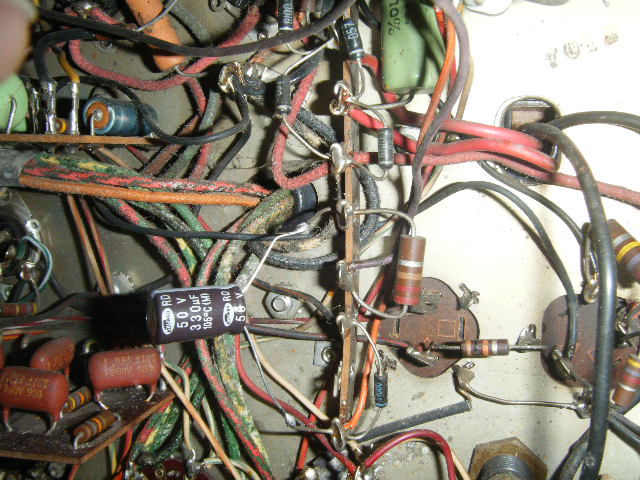
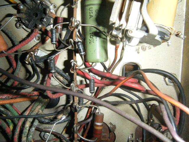
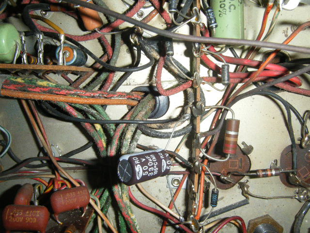
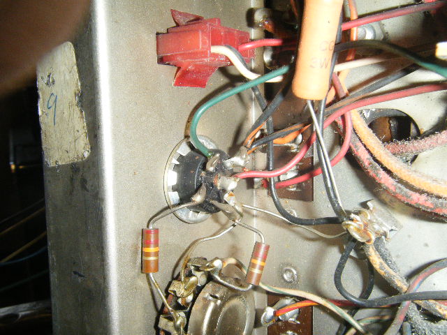
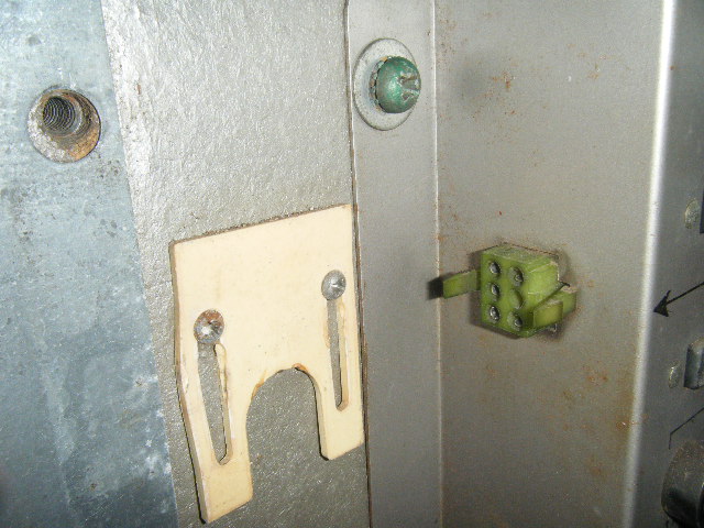
The round socket is where the volume control plugs in on the other side, i think the black/orange wire goes to pin 3 and it is spurred off down to the terminal post at the relay. There is no pin on the volume control connecting into pin three. The diode i measured in circuit and was fine, didn't measure it out of circuit. The square socket connects to the side of the power supply. I have attached some photos which show the socket, and general vicinity (terminal post) of the relay and also a very rough sketch. Two of the wires for the relay are disconnected as i was testing another one, the purple wire will appear faed in colour, the black orange wire beside the wire will appear orange (heat and time have faded the black
regards
clones
- Attachments
-
- terminal post
- Picture 218.jpg (119.39 KiB) Viewed 1275 times
-
- terminal post
- Picture 217.jpg (125.81 KiB) Viewed 1275 times
-
- terminal post and relay
- Picture 213.jpg (121.29 KiB) Viewed 1275 times
-
- terminal post at relay
- Picture 212.jpg (126.79 KiB) Viewed 1275 times
-
- six pin socket
- Picture 214.jpg (118.28 KiB) Viewed 1275 times
-
- side of power supply
- Picture 216.jpg (118.95 KiB) Viewed 1275 times
-
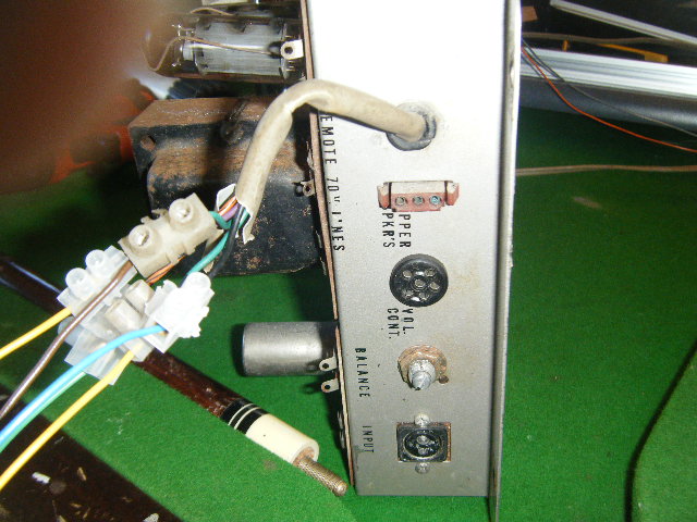
- side of amp
- Picture 215.jpg (116.59 KiB) Viewed 1275 times
-
- sketch
- untitled.JPG (17.63 KiB) Viewed 1275 times
-
clones
Topic author - Senior Member
- Posts: 582
- Joined: Thu Aug 11, 2011 11:29 am
- Location: County Louth, Ireland
Ron
just as an add on to my previous mail, i was thinking that at pin 3 where the black/orange wire is soldered at the six pin socket inside the amp and the fact that there is no wired pin inserted into to it from the volume control, maybe there should be something going in there. So where the black and orange wire goes from the microswitches (which is also looped in with the reject button) into the control box, i ran a wire from it to an to pin 3 on the six pin socket. Then i connected the two wires which i had removed from the existing relay in the amp and connected to an external relay, turned the machine on and the external relay energised. Not totally sure whether i am on the right track, need to reconnect everything up again and see if the relay energises and de-energises at the start and end of the record
regards
cclones
-
Ron Rich
- Forum Moderator
- Posts: 8196
- Joined: Sun May 06, 2007 11:31 pm
- Location: Millbrae (San Francisco area)CA, USA
Sorry--it makes no sense to me--
Ron Rich
Ron Rich
-
clones
Topic author - Senior Member
- Posts: 582
- Joined: Thu Aug 11, 2011 11:29 am
- Location: County Louth, Ireland
Ron
i know its a very convoluted story,
try this then
-existing relay is back and connected in the amp
-in photo 215 there is a volume control socket (6 pins) photo 214, pin 3 on the volume cable(not in photo)
-black/orange wire from power supply unit goes to pin 3 inside the amp and from there is connected up to terminal at bottom photo 217. When i mean by terminal, its the one i highlighted in the earlier schematic. This black/orange wire is connected up to the diode and the + of the cap and then to the relay
-purple wire from power supply is wired also to both to this relay and this terminal (photo 217 located between the resistor legs)
so what i did....., i soldered wire to pin3 of volume control which now sits into pin 3 of the six pin socket and connected it up to black/orage wire that microswitch controls, this wire is looped onto the reject button and the gripper reverse relay socket of the control box.
i had a preliminary trial run at it and the relay seems to energise on standby and release when record is played and energise at end of record.
hope that makes sense
possibly in the past someone made up a new voume control cable and left this wire out
regards
clones
-
Ron Rich
- Forum Moderator
- Posts: 8196
- Joined: Sun May 06, 2007 11:31 pm
- Location: Millbrae (San Francisco area)CA, USA
Sounds good to me--glad you "found" it. Ron Rich
-
clones
Topic author - Senior Member
- Posts: 582
- Joined: Thu Aug 11, 2011 11:29 am
- Location: County Louth, Ireland
thanks for your help Ron
Who is online
Users browsing this forum: Bing [Bot], JoeyDVDZ and 6 guests
It is currently Fri Oct 07, 2016 12:09 am